2. MIPI DSI
Overview
The The Display Serial Interface (DSI) is defined by the Mobile Industry Processor Interface Alliance (Mobile Industry Processor Interface alliance,MIPIAlliance) definitiona type ofhighspeedseriallineconnectport, mainneed toused to processingdeviceanddisplaymodulebetweenconnectconnect.
This chapter describes how to develop and debug an MIPI LCD panel on CVITEK processor solutions, helping customers develop MIPI LCD applications in an orderly and efficient way.
2.1. Environment Preparation
2.1.1. MIPI DSI Panel Interface
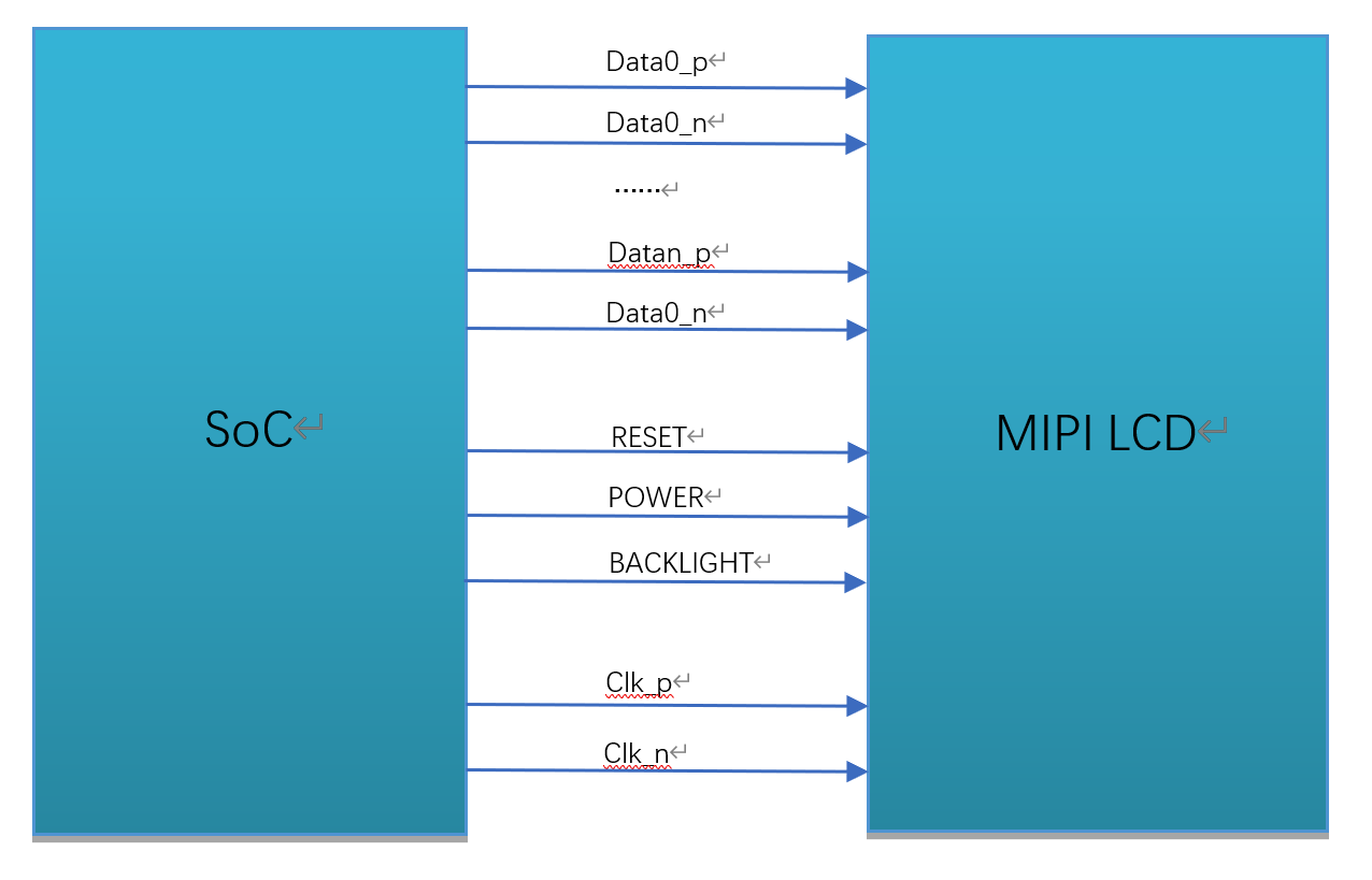
An MIPI DSI panel generally has the following signals, as shown in the figure.
MIPI clock line (CLK)
MIPI data lines (DATA), up to 4 lanes (only 1/2/4 lanes are supported)
Backlight control signal (BACKLIGHT)
Reset pin (RESET)
Panel power supply (POWER)
MIPI DSI interface wiring diagram
2.1.2. Hardware Wiring Check
Check the hardware wiring and confirm that it is correct. For pin differences, refer to the panel vendor specifications and schematic.
2.2. Configure the MIPI Panel
The preceding section covered the panel interface and wiring. This section describes the software configuration required for panel integration.
CVITEK hastwo types ofsolutionperform MIPIpanelforconnect, respectivelyisinu-bootandkernelinperform panel initialization, areadifferenceininu-bootinperform initializationafter, bootcandisplaycustomerlogo image, andwithpanelproductalmost allwillhasdisplay the logorequirement. actualapplicationinaccording torequirementchoose one of the twoitsone.
2.2.1. Configure the MIPI Panel in u-boot
u-bootMediumConfigure the MIPI PanelisthroughCVITEKdevelopmentshowlogocommand, devicepower-onafter, pressEnterenterU-Boot Commandsline, printenvcanviewtoshowlogocommand (notsameboardcommandwillhasareadifference) , bootcmdinbootinkernelbeforewillexecutethecommandperform panel initializationanddisplay the logo.
Example:
showlogo=mmc dev 0;mmc read 0x84080000 0xA000 0x400; cvi_jpeg 0x84080000 0x81800000 0x80000; startvo 0 8192 0;startvl 0 0x84080000 0x81800000 0x80000 32;setvobg 0 0xffffffff
this documentfocuses on explainingpanel initializationpart, display the logospecificpleasereference"CV184XbootimageuseGuide". where, panel initializationpartin"startvo 0 8192 0"inimplement.
2.2.1.1. Configure MIPI Tx Device Attributes
Implement a configuration header for each panel according to its specification and place it under u-boot-2021.10/include/cvitek/cvi_panels/. Customers can use the other header templates as a reference when adding a panel header.
combo_dev_cfg_sstructuredefinition
struct combo_dev_cfg_s {

  unsigned int devno;

  enum mipi_tx_lane_id lane_id[LANE_MAX_NUM];

  enum output_mode_e output_mode;

  enum video_mode_e video_mode;

  enum output_format_e output_format;

  struct sync_info_s sync_info;

  unsigned int pixel_clk;

  bool lane_pn_swap[LANE_MAX_NUM];

};
Member Name |
Description |
|---|---|
devno |
MIPI Tx device number; the default is 0 |
lane_id |
host and panel sidesLane numbercorrespondence, unuseduseLanefill-1that is, can . a total of5itemmember, sequentiallyrespectivelyrepresenthost sideMIPI_TX_0~MIPI_TX_4, actualfill incontentneed toaccording tocorrespondingtopanel sideMIPI lane number. for example, firstitemmemberishostMIPI_TX_0, checkcircuitschematic, correspondingtopanel sideMIPI lane3, thenfill inisMIPI_TX_LANE_3. correspondencenotcorrect, willcausepanelcannotlight up. |
output_mode |
MIPI Tx output mode; the default is OUTPUT_MODE_DSI_VIDEO |
video_mode |
MIPI Tx video mode; the default is BURST_MODE |
output_format |
MIPI Tx output format; the default is OUT_FORMAT_RGB_24_BIT |
sync_info |
MIPI Tx device synchronization information |
pixel_clk |
Pixel clock, in kHz. Formula: pixel_clk=(htotal*vtotal)*fps/1000 Where: htotal=vid_hsa_pixels+ vid_hbp_pixels+ vid_hfp_pixels+ vid_hline_pixels vtotal= vid_vsa_lines+ vid_vbp_lines+ vid_vfp_lines+ vid_active_lines fps:frame rate, default60 lane_clkaccording topixel_clkderive backward, conversionformula: lane_clk= pixel_clk*24/4/2(24meansRGB888eachpixeloccupy24bits, 4meansuse4itemData Lane, 2meansmipi clkisdual-edge triggered) |
lane_pn_swap |
MIPI TxLane P/Nextremeiswhether to swap true: swap false:notswap |
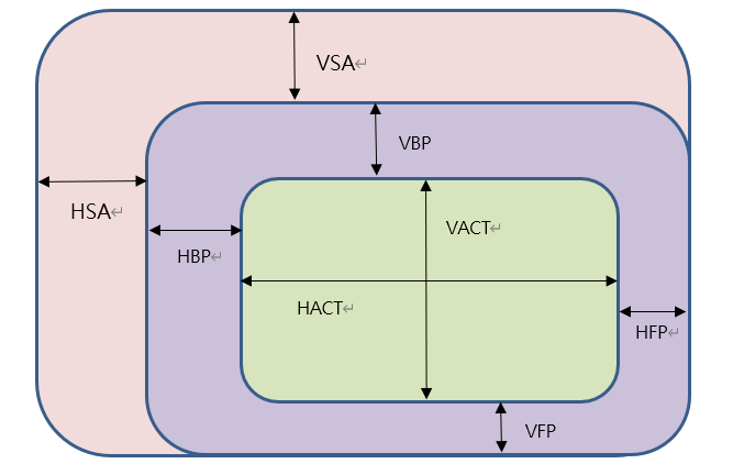
combo_dev_cfg_sMedium sync_info (MIPI Tx devicesynchronizationinformation) relatively difficultconfigure, belowdetailedIntroductionitconfiguration method. generallystartwillaccording topanelmanufacturerprovidespecificationdocumentfill inreferencevalue, alsohasproblemthenaccording tophenomenonadjust.
sync_info_sstructuredefinition
struct sync_info_s {

  unsigned short vid_hsa_pixels;
  unsigned short vid_hbp_pixels;
  unsigned short vid_hfp_pixels;
  unsigned short vid_hline_pixels;
  unsigned short vid_vsa_lines;
  unsigned short vid_vbp_lines;
  unsigned short vid_vfp_lines;
  unsigned short vid_active_lines;
  bool vid_vsa_pos_polarity;
  bool vid_hsa_pos_polarity;

};
Member Name |
Description |
|---|---|
vid_hsa_pixels |
Horizontal Sync Pulse(HSA), unitispixel |
vid_hbp_pixels |
Horizontal Blankingafterporch(HBP), unitispixel |
vid_hfp_pixels |
Horizontal Blankingbeforeporch(HFP), unitispixel |
vid_hline_pixels |
Horizontal active area(HACT), unitispixel |
vid_vsa_lines |
Vertical Sync Pulse(VSA), unitisline |
vid_vbp_lines |
Vertical Blankingafterporch(VBP), unitisline |
vid_vfp_lines |
Vertical Blankingbeforeporch(VFP), unitisline |
vid_active_lines |
Vertical active area(VACT), unitisline |
vid_vsa_pos_polarity |
Vertical active-signal polarity, 0isHighvalid, 1isLowvalid |
vid_hsa_pos_polarity |
Horizontal active-signal polarity, 0isHighvalid, 1isLowvalid |
MIPI DSIprotocolunderMIPIpixelareaillustration
hs_settle_sstructuredefinition
struct hs_settle_s {
  unsigned char prepare;
  unsigned char zero;
  unsigned char trail;
};
Member Name |
Description |
|---|---|
prepare |
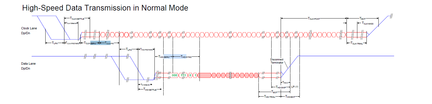
MIPI Tx preparesignal, default value6 |
zero |
MIPI Tx zerosignal, default value32 |
trail |
MIPI Tx trailsignal, default value1 |
MIPI Txtiming diagram
Example:
const struct combo_dev_cfg_s dev_cfg = {
  .devno = 0,
  .lane_id = {MIPI_TX_LANE_3, MIPI_TX_LANE_0, MIPI_TX_LANE_CLK, MIPI_TX_LANE_2, MIPI_TX_LANE_1},
  .lane_pn_swap = {false, false, false, false, false},
  .output_mode = OUTPUT_MODE_DSI_VIDEO,
  .video_mode = BURST_MODE,
  .output_format = OUT_FORMAT_RGB_24_BIT,
  .sync_info = {
    .vid_hsa_pixels = 30,
    .vid_hbp_pixels = 100,
    .vid_hfp_pixels = 100,
    .vid_hline_pixels = 800,
    .vid_vsa_lines = 4,
    .vid_vbp_lines = 16,
    .vid_vfp_lines = 10,
    .vid_active_lines = 1280,
    .vid_vsa_pos_polarity = false,
    .vid_hsa_pos_polarity = true,
  },
  .pixel_clk = 80958,
};
const struct hs_settle_s hs_timing_cfg = { .prepare = 6, .zero = 32, .trail = 1 };
2.2.1.2. Configure the Panel Initialization Sequence
panelgenerallyallhasinitializationprocess, MIPI LCD panelisthrough MIPI Tx D-PHY connectporttosendspecifiedtypedatapacket. initialization sequencebypanel manufacturerprovide.
panel initializationsequencecolumngenerallyincludingpixelformat, datarefreshdirection, Gamma configureetc., initialization sequenceineachoneCommandspecificmeaning, pleaseinpanelmanufacturerprovidespecificationdocumentororDriver IC Datasheetincheckfind. initialization sequenceisthroughMIPI TxData Lane0inLPmodeundersend, sendendafterwillswitchtoHSmode.
dsc_instr structuredefinition
struct dsc_instr {
  u8 delay;
  u8 data_type;
  u8 size;
  u8 *data;
};
panel manufacturerprovideinitialization sequencegenerallyhasregisteraddressandcorrespondingdata, need toaccording topanel manufacturergivesequencecolumn, populateData Types, dataaddressanddata.
Member Name |
Description |
|---|---|
delay |
sendcompletethiscommandafter, delaymillisecondsnumber |
data_type |
writecommandData Types, that is, DCS(DisplayCommandSet)(Commandset)inData Type. according todatacountselectData Types. type1, When onlyhasregisteraddressno hasdatawhen, Data Typesselect0x05; type2, hasregisteraddressandonedatawhen, Data Typesselect0x15 oror 0x23; type3, hasregisteraddressanddatacountgreater thanetc.more than twoitem, Data Typesgenerallyuse0x29oror0x39. generallycaseundercommonuse, specificusepleaseconsultpanel manufacturer. |
size |
registeraddressanddatacountsum of. for exampleWhen onlyhasoneregisteraddress, fill1; When hasoneregisteraddressand1itemdatafill2; oneregisteraddressand2itemdatafill3, according tothisanalogy. |
data |
commanddatapointer. registeraddressanddata. firstitemmustisregisteraddress, connectinaftersideisdata, datacanno hasororhasmultiple. |
Note: For commandData Typesparameterconfigureselect, need toconsultmanufacturer. If no hasobtaintomanufacturersupport, recommendno hasdatawhenselect 0x05, hasonedatawhenselect 0x15, multipledatawhenselect 0x29.
Example:
static u8 data_xxxx_0[] = { 0xFF, 0x98, 0x81, 0x03 };
static u8 data_xxxx_1[] = { 0x01, 0x00 };
static u8 data_xxxx_2[] = {0x02, 0x00 };
......
static u8 data_xxxx_n[] = { 0x11 };
static u8 data_xxxx_n+1[] = { 0x29 };

const struct dsc_instr dsi_init_cmds[] = {
  { .delay = 0, .data_type = 0x29, .size = 4, .data = data_xxxx_0 },
  { .delay = 0, .data_type = 0x15, .size = 2, .data = data_xxxx_1 },
  { .delay = 0, .data_type = 0x15, .size = 2, .data = data_xxxx_2 },
  ......
  { .delay = 120, .data_type = 0x05, .size = 1, .data = data_xxxx_n },
  { .delay = 20, .data_type = 0x05, .size = 1, .data = data_xxxx_n+1 },
}
2.2.1.3. Add Header File Includes
Add the newnew headerfileinclude, inu-boot-2021.10/include/cvitek/cvi_panels/cvi_panels.hinincreaseforonthe two sectionsinnew headerfileinclude.
Example:
#ifdef MIPI_PANEL_HX8394
#include "dsi_hx8394_evb.h"
static struct panel_desc_s panel_desc = {
  .panel_name = "HX8394-720x1280",
  .dev_cfg = &dev_cfg_hx8394_720x1280,
  .hs_timing_cfg = &hs_timing_cfg_hx8394_720x1280,
  .dsi_init_cmds = dsi_init_cmds_hx8394_720x1280,
  .dsi_init_cmds_size = ARRAY_SIZE(dsi_init_cmds_hx8394_720x1280)
};
#endif
2.2.1.4. Configure the MIPI Panel RESET Pin
inu-boot-2021.10/drivers/video/cvitek/cvi_mipi.cmipi_tx_set_combo_dev_cfgfunctioninincreaseRESET/POWER/BACKLIGHTcontrol.
MIPI panelgenerallyRESETpinuseis GPIO port. thereforeneed tofor GPIO portperform configure, at the same timeperform panelresetbitsoperation.
queryhardwareschematic, GetRESETpincorrespondingpinname.
compare with"CV184X_PINOUT_CN"findtopincorrespondingGPIOgroup numberandNo..
modifybuild/boards/default/dts/cv184x/cv184x_base.dtsiMediumvosectionpointresetiscorrespondingvalue.
configurationRESETtheuse GPIO resetbitsoperationtiming.
panelresetbitsoperationneed toreferencepaneldescriptiondocument, If noneresetbitsoperationororresetbitstimingwithpanelneed torequestnotmatch, ororlevelnotmatch, panelmaywillcannotlight upororworkingabnormality. generallyandwordswillishigh-low-highlevelchange, specificpleaserefer topanelspecificationdocument.
Example:
assumingpanelRESETpinisGPIOE 2, resetbitsvoltageisLow, in build/boards/default/dts/cv184x/cv184x_base.dtsimodify as follows:
reset-gpio = <&porte 2 GPIO_ACTIVE_LOW>;
configureas follows:
gpio_request_by_name(dev, "reset-gpio", 0, &priv->ctrl_gpios.disp_reset_gpio, GPIOD_IS_OUT | GPIOD_IS_OUT_ACTIVE);
operationas follows:
dm_gpio_set_value(&ctrl_gpios.disp_reset_gpio, ctrl_gpios.disp_reset_gpio.flags & GPIOD_ACTIVE_LOW ? 0 : 1);
mdelay(10);
dm_gpio_set_value(&ctrl_gpios.disp_reset_gpio, ctrl_gpios.disp_reset_gpio.flags & GPIOD_ACTIVE_LOW ? 1 : 0);
mdelay(10);
dm_gpio_set_value(&ctrl_gpios.disp_reset_gpio, ctrl_gpios.disp_reset_gpio.flags & GPIOD_ACTIVE_LOW ? 0 : 1);
mdelay(100);
thisthe effect of these lineswillwillisRESETpingenerateonehigh-low-highlevelchange
2.2.1.5. Configure the MIPI Panel POWER Pin
MIPIpanelPOWERcontrolgenerallyalsoisuseGPIO. usuallyonly need topullhighorpulllowpinlevelthat is, can controlMIPIpanelpower supply control. haspanelalsomaydirectlyconnectpower supply, thiswaywordssoftwarethennoneneed tocontrol.
configuration methodwithonsectionRESETpinmethodonecause
Example:
assumingpanelPOWERpinisGPIOE 1, workingvoltageisHigh, inbuild/boards/default/dts/cv184x/cv184x_base.dtsimodify as follows:
power-ct-gpio = <&porte 1 GPIO_ACTIVE_HIGH>;
ifnotneed toconfigurePOWERdirectlyconnectdelete it.
configureas follows:
gpio_request_by_name(dev, "power-ct-gpio", 0, &priv->ctrl_gpios.disp_power_ct_gpio, GPIOD_IS_OUT | GPIOD_IS_OUT_ACTIVE);
operationas follows:
dm_gpio_set_value(&ctrl_gpios.disp_power_ct_gpio, ctrl_gpios.disp_power_ct_gpio.flags & GPIOD_ACTIVE_LOW ? 0 : 1);
2.2.1.6. Configure the MIPI Panel BACKLIGHT Pin
MIPIpanelBACKLIGHTcanconfigureisGPIOororPWM.
2.2.1.6.1. configureisGPIO
configuration methodwithonsectionRESETpinmethodonecause
Example:
assumingpanelPWMpinisGPIOE 0, workingvoltageisHigh, inbuild/boards/default/dts/cv184x/cv184x_base.dtsimodify as follows:
pwm-gpio = <&porte 0 GPIO_ACTIVE_HIGH>;
ifnotneed toconfigurePOWERdirectlyconnectdelete it.
configureas follows:
gpio_request_by_name(dev, "pwm-gpio", 0, &priv->ctrl_gpios. disp_pwm_gpio, GPIOD_IS_OUT | GPIOD_IS_OUT_ACTIVE);
operationas follows:
dm_gpio_set_value(&ctrl_gpios.disp_pwm_gpio, ctrl_gpios.disp_pwm_gpio.flags & GPIOD_ACTIVE_LOW ? 0 : 1);
2.2.1.6.2. configureisPWM
MIPIpanelBACKLIGHTPWM is generally used to enable brightness adjustment.
queryhardwareschematic, GetBACKLIGHTpincorrespondingpinname.
inu-boot-2021.10/board/cvitek/cv181x/board.cboard_initfunctionin, configurationBACKLIGHTpinreusefunctionisPWMfunction.
compare with"CV184X Preliminary Datasheet"outsidescopedevicePWMchaptersectionregisterinformation, configurationPWMoutputperiod, duty cycle, Enable.
PWMbaseaddressinformation, itsremainingregisterinformationspecificpleasereference"CV184X Preliminary Datasheet", CV184Xhas3groupPWM, eachgroup6itemchannel
pwm0 |
0x030010a4 |
pwm1: |
0x030010d0 |
pwm2: |
0x03001058 |
Note:herePWM0~2isPWMgroup number, andschematicororpinlistinwriteisPWM0~PWM17, ifWhen viewtoPWM1, correspondingisondescribetableNo. 0groupfirstitemchannelPWM0_1.
Example:
assumingpanelBACKLIGHTpinisPWM8
devmem 0x030010A4 32 0x00000004 //复用相应的引脚为PWM

echo 2 > /sys/class/pwm/pwmchip6/export //配置待操作的PWM编号

echo 1000000 >/sys/class/pwm/pwmchip6/pwm2/period // 设置PWM一个周期的持续时间(单位ns)

echo 500000 >/sys/class/pwm/pwmchip6/pwm2/duty_cycle // 设置一个周期中的”ON”时间(单位ns),即占空比

echo 1 >/sys/class/pwm/pwmchip6/pwm2/enable // 使能 PWM 输出
2.2.1.7. Configure u-boot Environment Variables
modifyu-boot-2021.10/include/configs/cv184x-asic.hinu-bootenvironmentvariableparameter
Example:
#define SHOWLOGOCMD LOAD_LOGO CVI_JPEG START_VO START_VL SET_VO_BG
LOAD_LOGOwillimagebyMISCpartitionreadtoDRAM, CVI_JPEGwillimageparsetospecifiedposition, START_VOandSTART_VLEnable VOandwilllogodisplayincenterinposition, SET_VO_BGSetVObackground color, panelexceptlogoofoutsideOtherareabythiscolorpopulate.
2.2.1.8. Replace the Logo Image
willcustomerlogo imageplacesetinthepathunderbuild/tools/common/bootlogo/, compileexecutebuild_allafterwillcopytoimagegeneratepathunder.
Note: I80panelneed to24bit BMPimage, Otherneed toYUV420formatjpg .
2.2.1.9. Build, Program, and Verify
inondescribestepallcompleteafter, recompileburningnewu-boot. power-on, pressEnterenterU-Boot Commandsline. executerun showlogo, if successfulcanviewtopaneldisplayoutlogo image. If unuseddisplayoutlogo, pleaseconfirmwithunder.
Confirm that the backlight is on
confirmRESETpinlevelstatushasreachexpected
Confirm that panel power is normal
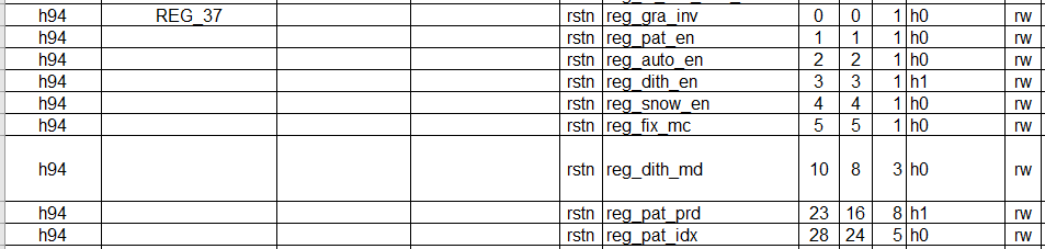
executemw 0x0a094094 0x0701000a, OutputVOtest pattern, falseifpanel initializationsuccess, you will seetocolorbar
test patternregisteras followsFigure
findhaswithonanyabnormalitypleasego back andcheckthisbeforeflowiswhethersetcorrectandreachexpected.
if the aboveonallunusedfindabnormality, recommendviewDriver IC datasheetordirectlyconnectconsultpanel manufacturer, how to enablepanelBIST mode, usuallyisadjustinitialization sequenceinaregistervalue, willdisplaycolorbaretc..
falseifBIST modenotnormal, thenneed tothencheckMIPI Laneorder, RESET, POWER, PWMetc.iswhetherconfigurecorrect, andusemultimeter/oscilloscopeetc.confirmcircuitlevelstatusas expected, if allas expected, thenmayisa panel problem, pleaseconsultpanel manufacturer.
falseifBISTnormal, thendescriptionwithonconfigurecorrect, hardwarecircuitno hasabnormality, at this timeusuallyneed toadjustsync_info_sineachparameter.
2.2.2. Configure the MIPI Panel in the Kernel
Configure the MIPI Panel in the Kernelmethodwithinu-bootinalmostisoneway, onlyisimplementflownotoneway. When noneneed todisplay the logowhen, can selectthis method.
anotheroutside, alsocanfirstusekernelbring up using this method, then porttou-boot, avoid frequentburningu-boot.
kernelinforconnect MIPIpanelbasic block diagramFigure
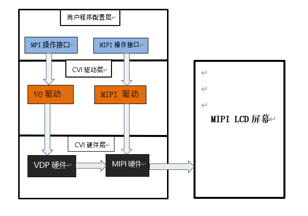
2.2.2.1. Configure MIPI Tx Device Attributes
Implement a configuration header for each panel according to its specification and place it under cvi_mpi/component/panel/. Customers can use the other header templates as a reference when adding a panel header.
See 2.2.1.1section
2.2.2.2. Configure the Panel Initialization Sequence
See 2.2.1.2section
2.2.2.3. Add Header File Includes
Add the newnew headerfileinclude, incvi_mpi/sample_app/panel/sample_panel.cinincreaseforonthe two sectionsinnew headerfileinclude.
Example:
ifneed topointpanelHX8394_EVB, First, incvi_mpi/sample_app/panel/sample_panel.hMediumincludethepanelheader filedsi_hx8394_evb.h, Then, ensurecvi_mpi/sample_app/panel/sample_panel.cfilein characterarraystatic char *s_panel_model_type_arr[ ]inhas"HX8394_EVB"character, no hasthenitselfAdd , connectwithinthefilepanelenumerationtypePANEL_MODELinAdd withthecharacterindexvaluemutualetc.enumeration valueHX8394_EVB, Finally, inSAMPLE_SET_PANEL_DESCfunctioninAdd the newpanelrelatedparameterperform callcase, as shown below:
case DSI_PANEL_HX8394_EVB:
        g_panel_desc.panel_type = PANEL_MODE_DSI;
        g_panel_desc.stdsicfg.dev_cfg = &dev_cfg_hx8394_720x1280;
        g_panel_desc.stdsicfg.hs_timing_cfg = &hs_timing_cfg_hx8394_720x1280;
        g_panel_desc.stdsicfg.dsi_init_cmds = dsi_init_cmds_hx8394_720x1280;
        g_panel_desc.stdsicfg.dsi_init_cmds_size = ARRAY_SIZE(dsi_init_cmds_hx8394_720x1280);
        break;
2.2.2.4. Configure the MIPI Panel RESET, POWER, and BACKLIGHT Pins
method1:
inpathbuild/boards/default/dts/cv184x/underfindtocorrespondingdtsfile, configurationMIPI Txgpioinformation, If no hasthepin, then directlyconnectnotwritethat is, can .
Example:
mipi_tx: mipi_tx {
        compatible = "cvitek,mipi_tx";
        reset-gpio = <&porte 2 GPIO_ACTIVE_LOW>;
        pwm-gpio = <&porte 0 GPIO_ACTIVE_HIGH>;
        power-ct-gpio = <&porte 1 GPIO_ACTIVE_HIGH>;
        clocks = <&clk CV181X_CLK_DISP_VIP>, <&clk CV181X_CLK_DSI_MAC_VIP>;
        clock-names = "clk_disp", "clk_dsi";
};
Note:
pwm-gpio = <&porte 0 GPIO_ACTIVE_HIGH>;
isdebugconvenient, The backlight can first useGPIOcontrol, be sure to firstnotneed toinu-bootinconfigurepinmuxisPWMfunction, otherwisemaycannotcontrol.
lateraccording torequirement, If need toadjustluma, theninu-bootinconfigurepinmuxfunctionisPWM, deletedtsinthisline, at the same timeappinusePWMmethodcontrol.
systembootafterloadMIPI Txdrivermethod (generallywillautomaticload, can firstuselsmodviewiswhetheralreadyload) :
insmod /mnt/system/ko/cvi_mipi_tx.ko
thiswayWhen driverloadafter, willaccording todtsinGPIOinformation, automaticrequestpleasetheseGPIO, andinitializationbecomecorrespondinglevelstatus.
method2:
noneneed tomodifyinkerneldtsfile.
systembootloadMIPI Txdrivermethod:
insmod /mnt/system/ko/cvi_mipi_tx.ko gpio=354,0,353,1,352,1
these threeGPIOsequentiallyrespectivelyisRESET, POWER, PWM
When driverloadafter, driverwillpreferentiallyusegpioparameterininformationautomaticrequestpleaseGPIOnumbercorrespondingGPIO, andinitializationbecomeitsafterlevelstatus. If no haswritegpioParameters, driverwillaccording todtsinGPIOinformationrequestpleaseGPIO. If no hasthepin, thenGPIOnumberandlevelstatusallwrite-1that is, can .
sameway, isdebugconvenient, The backlight can first useGPIOcontrol, firstnotneed toinu-bootinconfigurepinmuxisPWMfunction. laterneed toadjustluma, theninu-bootinconfigurepinmuxfunctionisPWM, at the same timeappinusePWMmethodcontrol, andwillthirditemGPIOnumberandlevelstatuswritebecome-1that is, can .
method3:
directlyconnectinapplicationlayerdirectlyconnectcontrolGPIO.
Example: assumingreset: GPIOE2, pwm: GPIOE0, power: GPIOE1, canusecat /sys/kernel/debug/gpioCommandviewchipgpioconfiguration, can in sequenceobtaintogpiochip0togpiochip4numberrange, in sequencecorrespondingwithGPIOAtoGPIOEnumberrange, If obtainoutgpiochip4rangeis352to383, thenFor requiredpullGPIOE2tosay, belowechooperationnumbercodecan by352+2=354obtainto.
thereforeneed towithunderoperationpullcorrespondingpin:
1. echo 352 > /sys/class/gpio/export
   echo 353 > /sys/class/gpio/export
   echo 354 > /sys/class/gpio/export
2. echo out > /sys/class/gpio/gpio352/direction
   echo out > /sys/class/gpio/gpio353/direction
   echo out > /sys/class/gpio/gpio354/direction
3. echo 1 > /sys/class/gpio/gpio352/value
   echo 1 > /sys/class/gpio/gpio353/value
   echo 1 > /sys/class/gpio/gpio354/value
   echo 0 > /sys/class/gpio/gpio354/value
   echo 1 > /sys/class/gpio/gpio354/value
Note:
isdebugconvenient, The backlight can first useGPIOcontrol, be sure to firstnotneed toinu-bootinconfigurepinmuxisPWMfunction, otherwisemaycannotcontrol.
lateraccording torequirement, If need toadjustluma, inu-bootinconfigurepinmuxfunctionisPWM, at the same timeappinusePWMmethodcontrol.
2.2.2.5. Build verification
executebuild_middlewareCompilationmiddleware, inpathcvi_mpi/sample_app/panel/underwillgeneratesample_panelcan executefile. theprogramandinu-bootMedium"startvo 0 65536 0"operationisoneway, switchtoLPmode, SetMIPI TxdeviceattributeandthroughData Lane0topanelsendinitialization sequence, Then, switch backHSmode.
willsample_panelcopytodevice, executecommand./sample_panelafterwillpop upoutthecommandProcedure, presspromptrunthat is, can .
Example:./sample_panel –panel=HX8394_EVB
Note:
RESETinitiallevelsetislow, willneed tohigh-low-hightimingchange.
RESETinitiallevelsetishigh, willneed tolow-high-lowtimingchange.
EnableVOtest pattern, registeras followsFigure . executedevmem 0x0a094094 32 0x0701000awillwillviewtocolorbar.
If colorbarunusednormaldisplay, pleasego back andcheckthisbeforeflowiswhethersetcorrectandreachexpected.
falseifthisbeforeflowallunusedfindabnormality, recommendviewDriver IC datasheetordirectlyconnectconsultpanel manufacturer, how to enablepanelBIST mode, usuallyisadjustinitialization sequenceinaregistervalue, willdisplaycolorbaretc..
falseifBIST modenotnormal, thenneed tothencheckMIPI Laneorder, RESET, POWER, PWMetc.iswhetherconfigurecorrect, andusemultimeter/oscilloscopeetc.confirmcircuitlevelstatusas expected, if allas expected, thenmayisa panel problem, pleaseconsultpanel manufacturer.
falseifBISTnormal, thendescriptionwithonconfigurecorrect, hardwarecircuitno hasabnormality, at this timeusuallyneed toadjustsync_info_sineachparameter.
2.2.3. Configure the MIPI Panel in the Dual-system Environment
Configure the MIPI Panel in the Dual-system Environmentmethodandinondescribesinglesysteminalmostisoneway, onlyishasonesomesmallareadifference. belowdescriptiononeunderwheredifferencesame.
forconnectMIPIpanelbasic block diagramFigure
where, onFigure VOwithMIPIdriverallinsmallkernelaliosincomplete.
2.2.3.1. Configure MIPI Tx Device Attributes
Implement a configuration header for each panel according to its specification and place it atcvi_mpi/component/panel/and cvi_alios/components/cvi_mmf_sdk/cvi_panel/under, customercanrefer toitsremainingheader filetemplateadd its ownpanelHeader files.
See 2.2.1.1section
2.2.3.2. Enable the Configuration Switch in cvi_alios
incvi_alios/solutions/{normboot/fastboot}/customization/{project_config}/package.yaml.turnkeyinenablecorrespondingchip andpaneltypeswitch,
Example, If selectCONFIG_CV1842HP_GC8613chip, CONFIG_PANEL_HX8394panel, thenenableas followsswitch:
CONFIG_CV1842HP_GC8613: 1

CONFIG_PANEL_HX8394: 1
NoteCONFIG_CHIP_cv1842hpchipIf need toat the same timesupportssensorandpanel, need tochangeinstallhardware, andpressneed tomodifycvi_alios/solutions/normboot/customization/cv1842hp_gc8613/src/custom_platform.c Medium_MipiTxPinmux()connectin the interfacepinreuse.
2.2.3.3. Configure the Panel Initialization Sequence
See 2.2.1.2section
2.2.3.4. Add Header File Includes
See 2.2.2.3section
2.2.3.5. Configure the MIPI Panel RESET, POWER, and BACKLIGHT Pins
incvi_alios/solutions/normboot/customization/cv1842hp_gc8613/src/custom_platform.cMedium_MipiTxPinmuxconnectin the interface Add forRESET, POWER, BACKLIGHTpinreuse, Then, directlyconnectinapplicationlayerdirectlyconnectcontrolGPIO.
Example:
For CONFIG_CHIP_cv1842hpchip, generallypullpinis: reset: GPIOE2, pwm: GPIOE0, power: GPIOE01.
thereforeneed towithunderoperationpullcorrespondingpin:
devmem 0x03022004 32 0x0
devmem 0x03022000 32 0x0
echo 352 > /sys/class/gpio/export
echo 353 > /sys/class/gpio/export
echo 354 > /sys/class/gpio/export
echo out > /sys/class/gpio/gpio352/direction
echo out > /sys/class/gpio/gpio353/direction
echo out > /sys/class/gpio/gpio354/direction
echo 1 > /sys/class/gpio/gpio354/value
echo 1 > /sys/class/gpio/gpio352/value
echo 1 > /sys/class/gpio/gpio353/value
echo 0 > /sys/class/gpio/gpio354/value
echo 1 > /sys/class/gpio/gpio354/value
For CONFIG_CHIP_cv1842cpchip, generallypullpinis: reset: GPIOA15, pwm: GPIOA18, power: GPIOA19.
thereforeneed towithunderoperationpullcorrespondingpin:
devmem 0x0300103c 32 0x3
devmem 0x03001068 32 0x3
devmem 0x03001064 32 0x3
echo 495 > /sys/class/gpio/export
echo 498 > /sys/class/gpio/export
echo 499 > /sys/class/gpio/export
echo out > /sys/class/gpio/gpio495/direction
echo out > /sys/class/gpio/gpio498/direction
echo out > /sys/class/gpio/gpio499/direction
echo 1 > /sys/class/gpio/gpio495/value
echo 1 > /sys/class/gpio/gpio498/value
echo 1 > /sys/class/gpio/gpio499/value
echo 0 > /sys/class/gpio/gpio495/value
echo 1 > /sys/class/gpio/gpio495/value
ondescribecodeindevmemwriteregisterCommandisisreusecorrespondingpin, If alreadycompleterelatedreuse, can notexecutetheCommand.
2.2.3.6. Build verification
See 2.2.2.5section