2. MIPI User Guide
2.1. Overview
MIPI Rx can receive differential and DC (TTL) interface data, convert it to pixel data, and pass it to the next ISP module. Differential signals support MIPI-CSI input. DC signals support Sensor RAW12, BT1120, BT656, and BT601.
2.2. Important Concepts
MIPI
The Mobile Industry Processor Interface (MIPI) is a communication interface that uses the D-PHY transmission specification at the physical layer and CSI-2 at the protocol layer.
Lane
The physical layer uses a pair of high-speed differential lines to connect the transmitter and receiver. A lane can carry a clock or data. 1C4D means one clock lane and four data lanes.
LVDS
Low Voltage Differential Signaling (LVDS) here generally refers to the sub-LVDS and HiSPi variants developed from LVDS, which distinguish blanking and active data through synchronization codes.
Synchronization Code
MIPI-CSI uses standard short packets as synchronization signals. LVDS uses sync codes as synchronization signals. LVDS has two synchronization modes:
Use SOF/EOF to indicate the start and end of a frame.
Use SOL/EOL to indicate the start and end of a line.
Figure 1-1 SOF/EOF/SOL/EOL Synchronization

Use SAV invalid and EAV invalid to indicate the start and end of VBLANK. Use SAV valid and EAV valid to indicate the start and end of valid data (information line, H.OB, and pixel data).
Figure 1-2 SAV/EAV Synchronization

DOI
SONY interleaved WDR mode, fully named Digital Overlap.
2.3. Function Description
MIPI RX supports one MIPI-CSI input with up to four lanes or two inputs with up to two lanes each. The interface supports lane swapping and P/N swapping for differential signals. When using two differential inputs, MIPIRX# pins 0 to 2 must be in one input group and pins 3 to 5 in the other. MIPI RX also supports parallel inputs such as sensor TTL, BT1120, BT656, and BT601, and supports lane-function swapping except for the clock. The lane distribution is shown below:
Table 1-1 BT Interface Distribution. BGA packages support VI0 to VI2; QFN packages support VI0.
VIO |
PAD NAME |
VI1 |
PAD NAME |
VI2 |
PAD NAME |
|---|---|---|---|---|---|
VIO_CLK |
MIPIRX4N |
VI1_CLK |
VIVO_CLK |
VI2_CLK |
VIDO_CLK |
VI0_D[0] |
MIPIRX4P |
VI1_D[0] |
VIVO_D0 |
VI2_D[0] |
VIVO_D0 |
VI0_D[1] |
MIPIRX3N |
VI1_D[1] |
VIVO_D1 |
VI2_D[1] |
VIVO_D1 |
VI0_D[2] |
MIPIRX3P |
VI1_D[2] |
VIVO_D2 |
VI2_D[2] |
VIVO_D2 |
VI0_D[3] |
MIPIRX2N |
VI1_D[3] |
VIVO_D3 |
VI2_D[3] |
VIVO_D3 |
VI0_D[4] |
MIPIRX2P |
VI1_D[4] |
VIVO_D4 |
VI2_D[4] |
VIVO_D4 |
VI0_D[5] |
MIPIRX1N |
VI1_D[5] |
VIVO_D5 |
VI2_D[5] |
VIVO_D5 |
VI0_D[6] |
MIPIRX1P |
VI1_D[6] |
VIVO_D6 |
VI2_D[6] |
VIVO_D6 |
VI0_D[7] |
MIPIRX0N |
VI1_D[7] |
VIVO_D7 |
VI2_D[7] |
VIVO_D7 |
VI0_D[8] |
MIPIRX0P |
VI1_D[8] |
VIVO_D8 |
||
VI0_D[9] |
MIPI_TXM0 |
VI1_D[9] |
VIVO_D9 |
||
VI0_D[10] |
MIPI_TXP0 |
VI1_D[10] |
VIVO_D10 |
||
VI0_D[11] |
MIPI_TXM1 |
VI1_D[11] |
MIPIRX5N |
||
VI0_D[12] |
MIPI_TXP1 |
VI1_D[12] |
MIPIRX5P |
||
VI0_D[13] |
MIPI_TXM2 |
VI1_D[13] |
MIPIRX4N |
||
VI0_D[14] |
MIPI_TXP2 |
VI1_D[14] |
MIPIRX4P |
||
VI1_D[15] |
MIPIRX3N |
||||
VI1_D[16] |
MIPIRX3P |
||||
VI1_D[17] |
MIPIRX2N |
||||
VI1_D[18] |
MIPIRX2P |
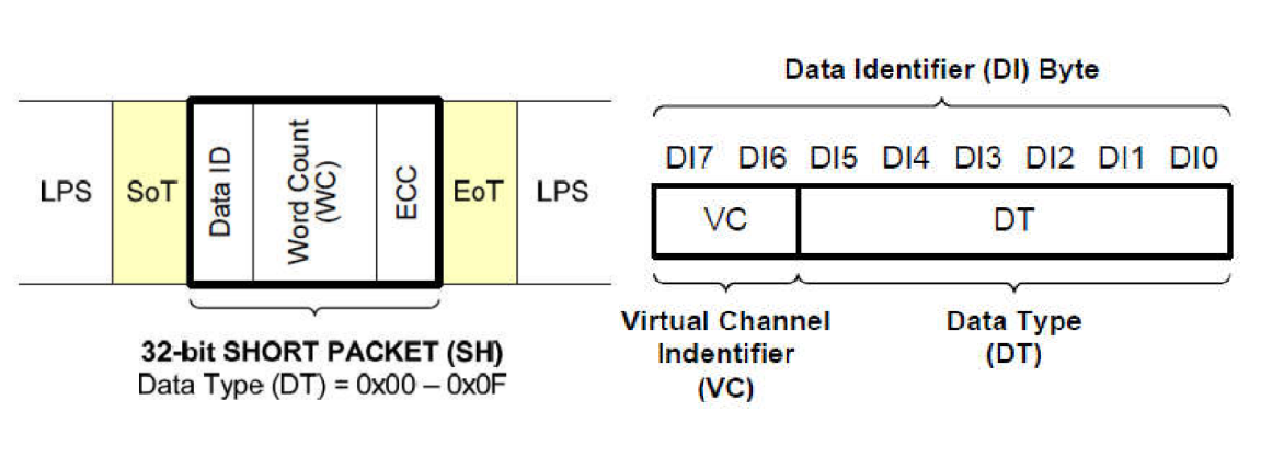
MIPI RX supports MIPI-CSI demultiplexing (CSI Demux) and can receive channel data with different channel IDs.
Figure 1-3 MIPI-CSI Channel IDs
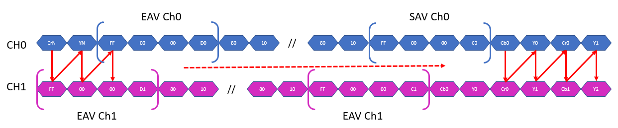
MIPI RX supports BT-interface demultiplexing (BT Demux). The input packs data from different channels in BT656 byte-interleaved format; MIPI RX restores each channel and extracts valid data with the corresponding synchronization code. This mode supports only single-edge sampling (SDR).
Figure 1-4 Inputs Supported by BT Demux Mode
2.4. API Reference
MIPI Rx provides sensor-timing integration and an ioctl interface. The available commands are as follows:
CVI_MIPI_SET_HS_MODE: Set the MIPI lane distribution mode.
CVI_MIPI_SET_DEV_ATTR :Set MIPI and parallel-interface device attributes.
CVI_MIPI_RESET_SENSOR :Reset the sensor.
CVI_MIPI_UNRESET_SENSOR :Release sensor reset.
CVI_MIPI_RESET_MIPI :Reset MIPI Rx.
CVI_MIPI_ENABLE_SENSOR_CLOCK: Enable the SENSOR clock.
CVI_MIPI_DISABLE_SENSOR_CLOCK :Disable SENSORclock.
CVI_MIPI_SET_CROP_TOP :Discard the first N lines of each frame.
CVI_MIPI_SET_WDR_MANUAL :Enable WDR manual mode.
CVI_MIPI_SET_LVDS_FP_VS: Set the VSYNC generation point in LVDS.
MIPI Tx provides display-panel and cascade integration. The available functions are as follows:
mipi_tx_cfg :Configure the MIPI TX device.
mipi_tx_send_cmd :Send a command to MIPI TX.
mipi_tx_recv_cmd :Receive a command from MIPI TX.
mipi_tx_enable :Enable MIPI TX.
mipi_tx_disable :Disable MIPI TX.
mipi_tx_set_hs_settle :Set the HS settle configuration.
mipi_tx_get_hs_settle :Get the HS settle configuration.
mipi_tx_suspend :Suspend MIPI TX.
mipi_tx_resume :Resume MIPI TX.
2.4.1. CVI_MIPI_SET_HS_MODE
[Description]
This function has been replaced by CVI_MIPI_SET_DEV_ATTR.
2.4.2. CVI_MIPI_SET_DEV_ATTR
[Description]
Set MIPI and parallel-interface device attributes.
[Parameters]
#define CVI_MIPI_SET_DEV_ATTR _IOW(CVI_MIPI_IOC_MAGIC, 0x01, struct combo_dev_attr_t)
[Definition]
Pointer to a struct combo_dev_attr_t.
[Return Value]
Return Value |
Description |
|---|---|
0 |
Success |
-1 |
Failure; errno is set. |
[Processor Differences]
None
[Requirements]
Header file: cvi_vip_cif.h
[Note]
Before configuring CVI_MIPI_SET_DEV_ATTR, use the ISP interface to enable the MIPI_RX clock. See the related ISP documentation for details.
exceptconfigureCVI_MIPI_SET_DEV_ATTRbefore, alsoneed toconfigurewithunderconnectport.
Reset MIPI: use CVI_MIPI_RESET_MIPI.
Enable the Sensor clock: use CVI_MIPI_ENABLE_SENSOR_CLOCK.
Reset the Sensor: use CVI_MIPI_RESET_SENSOR.
Release Sensor reset: use CVI_MIPI_UNRESET_SENSOR.
recommendconfigureflowas follows:
Enable the ISP clock.
Reset the connected Sensor.
Reset MIPI Rx.
Configure MIPI Rx device attributes.
Enable the clock connected to the Sensor.
Release reset for the connected Sensor.
recommendexitprogramas follows:
Reset the connected Sensor.
Disable the clock connected to the Sensor.
Reset MIPI Rx.
Disable the ISP clock.
Operating the Sensor reset and clock signal lines affects every Sensor connected to those lines.
[Related data types and interfaces]
CVI_MIPI_RESET_MIPI
CVI_MIPI_ENABLE_SENSOR_CLOCK disables the ISP clock.
CVI_MIPI_DISABLE_SENSOR_CLOCK
CVI_MIPI_RESET_SENSOR
CVI_MIPI_UNRESET_SENSOR
2.4.3. CVI_MIPI_RESET_SENSOR
[Description]
Reset the sensor
[Definition]
#define CVI_MIPI_RESET_SENSOR _IOW(CVI_MIPI_IOC_MAGIC, 0x05, unsigned int)
[Parameters]
unsigned int. Sensorresetbitssignallinenumber.
[Return Value]
Return Value |
Description |
|---|---|
0 |
Success |
-1 |
Failure; errno is set. |
[Processor Differences]
None
[Requirements]
Header file: cvi_vip_cif.h
[Note]
Sensorresetbitssignalbindincorrespondingdts.
mipi_rx: cif
{
  compatible = "cvitek,cif";
  reg = <0x0 0x0a0c2000 0x0 0x2000>, <0x0 0x0a0d0000 0x0 0x1000>,<0x0 0x0a0c4000 0x0 0x2000>;
  reg-names = "csi_mac0", "csi_wrap0", "csi_mac1";
  interrupts = <GIC_SPI 155 IRQ_TYPE_LEVEL_HIGH>,
               <GIC_SPI 156 IRQ_TYPE_LEVEL_HIGH>;
  interrupt-names = "csi0", "csi1";
  snsr-reset = <&porta 2 GPIO_ACTIVE_LOW>, <&porta 2 GPIO_ACTIVE_LOW>;
  resets = <&rst RST_CSIPHY0>, <&rst RST_CSIPHY1>,
         <&rst RST_CSIPHY0RST_APB>, <&rst RST_CSIPHY1RST_APB>;
  reset-names = "phy0", "phy1", "phy-apb0", "phy-apb1";
  clocks = <&clk CV181X_CLK_CAM0>, <&clk CV181X_CLK_CAM1>, <&clk CV181X_CLK_SRC_VIP_SYS_2>;
  clock-names = "clk_cam0", "clk_cam1", "clk_sys_2";
};
2.4.4. CVI_MIPI_UNRESET_SENSOR
[Description]
Release sensor reset.
[Definition]
#define CVI_MIPI_UNRESET_SENSOR _IOW(CVI_MIPI_IOC_MAGIC, 0x06, unsigned int)
[Parameters]
unsigned int. Sensorresetbitssignallinenumber.
[Return Value]
Return Value |
Description |
|---|---|
0 |
Success |
-1 |
Failure; errno is set. |
[Processor Differences]
None
[Requirements]
Header file: cvi_vip_cif.h
[Note]
Sensorresetbitssignalbindincorrespondingdts.
mipi_rx: cif
  {
    compatible = "cvitek,cif";
    reg = <0x0 0x0a0c2000 0x0 0x2000>, <0x0 0x0a0d0000 0x0 0x1000>,
          <0x0 0x0a0c4000 0x0 0x2000>;
    reg-names = "csi_mac0", "csi_wrap0", "csi_mac1";
    interrupts = <GIC_SPI 155 IRQ_TYPE_LEVEL_HIGH>,
                  <GIC_SPI 156 IRQ_TYPE_LEVEL_HIGH>;
    interrupt-names = "csi0", "csi1";
    snsr-reset = <&porta 2 GPIO_ACTIVE_LOW>, <&porta 2 GPIO_ACTIVE_LOW>;
    resets = <&rst RST_CSIPHY0>, <&rst RST_CSIPHY1>,
            <&rst RST_CSIPHY0RST_APB>, <&rst RST_CSIPHY1RST_APB>;
    reset-names = "phy0", "phy1", "phy-apb0", "phy-apb1";
    clocks = <&clk CV181X_CLK_CAM0>, <&clk CV181X_CLK_CAM1>, <&clk CV181X_CLK_SRC_VIP_SYS_2>;
    clock-names = "clk_cam0", "clk_cam1", "clk_sys_2";
  };
2.4.5. CVI_MIPI_RESET_MIPI
[Description]
Reset MIPI_Rx.
[Definition]
#define CVI_MIPI_RESET_MIPI _IOW(CVI_MIPI_IOC_MAGIC, 0x07, unsigned int)
[Parameters]
unsigned int. MIPI_Rxdevicenumber.
[Return Value]
Return Value |
Description |
|---|---|
0 |
Success |
-1 |
Failure; errno is set. |
[Processor Differences]
None
[Requirements]
Header file: cvi_vip_cif.h
[Note]
None
2.4.6. CVI_MIPI_ENABLE_SENSOR_CLOCK
[Description]
Enable the Sensor clock.
[Definition]
#define CVI_MIPI_ENABLE_SENSOR_CLOCK _IOW(CVI_MIPI_IOC_MAGIC, 0x10, unsigned int)
[Parameters]
unsigned int. MIPI_Rxdevicenumber.
[Return Value]
Return Value |
Description |
|---|---|
0 |
Success |
-1 |
Failure; errno is set. |
[Processor Differences]
None
[Requirements]
Header file: cvi_vip_cif.h
[Note]
None
2.4.7. CVI_MIPI_DISABLE_SENSOR_CLOCK
[Description]
Disable the Sensor clock.
[Definition]
#define CVI_MIPI_DISABLE_SENSOR_CLOCK _IOW(CVI_MIPI_IOC_MAGIC, 0x11, unsigned int)
[Parameters]
unsigned int. MIPI_Rxdevicenumber.
[Return Value]
Return Value |
Description |
|---|---|
0 |
Success |
-1 |
Failure; errno is set. |
[Processor Differences]
None
[Requirements]
Header file: cvi_vip_cif.h
[Note]
None
2.4.8. CVI_MIPI_SET_CROP_TOP
[Description]
Discard the first N lines of each frame
[Definition]
#define CVI_MIPI_SET_WDR_MANUAL _IOW(CVI_MIPI_IOC_MAGIC, 0x21, struct crop_top_s)
[Parameters]
struct crop_top_s
[Return Value]
Return Value |
Description |
|---|---|
0 |
Success |
-1 |
Failure; errno is set. |
[Processor Differences]
None
[Requirements]
Header file: cvi_vip_cif.h
[Note]
None
2.4.9. CVI_MIPI_SET_WDR_MANUAL
[Description]
Enable WDR manual mode.
[Definition]
#define CVI_MIPI_SET_WDR_MANUAL _IOW(CVI_MIPI_IOC_MAGIC, 0x21, struct manual_wdr_s)
[Parameters]
struct manual_wdr_s
[Return Value]
Return Value |
Description |
|---|---|
0 |
Success |
-1 |
Failure; errno is set. |
[Processor Differences]
None
[Requirements]
Header file: cvi_vip_cif.h
[Note]
None
2.4.10. CVI_MIPI_SET_LVDS_FP_VS
[Description]
Set the VSYNC generation point in sub-LVDS.
[Definition]
#define CVI_MIPI _SET_LVDS_FP_VS _IOW(CVI_MIPI_IOC_MAGIC, 0x22, struct vsync_gen_s)
[Parameters]
struct vsync_gen_s
[Return Value]
Return Value |
Description |
|---|---|
0 |
Success |
-1 |
Failure; errno is set. |
[Processor Differences]
None
[Requirements]
Header file: cvi_vip_cif.h
[Note]
None
2.4.11. mipi_tx_cfg
[Description]
Configure the MIPI TX device.
[Definition]
int mipi_tx_cfg(int fd, struct combo_dev_cfg_s *dev_cfg)
[Parameters]
Parameter Name |
Description |
Input/Output |
|---|---|---|
fd |
Framebuffer device file descriptor. |
Input |
dev_cfg |
deviceconfigureinformation. |
Input |
[Return Value]
Return Value |
Description |
|---|---|
0 |
Success |
-1 |
Failure; errno is set. |
[Requirements]
Header files:cvi_mipi_tx.h, cvi_comm_mipi_tx.h
Library file:libmipi_tx.a
[Note]
None
[Example]
None
[Related Topics]
None
2.4.12. mipi_tx_send_cmd
[Description]
Send a command to MIPI TX.
[Definition]
int mipi_tx_send_cmd(int fd, struct cmd_info_s *cmd_info)
[Parameters]
Parameter Name |
Description |
Input/Output |
|---|---|---|
fd |
Framebuffer device file descriptor. |
Input |
cmd_info |
commandinformation. |
Input |
[Return Value]
Return Value |
Description |
|---|---|
0 |
Success |
-1 |
Failure; errno is set. |
[Requirements]
Header files:cvi_mipi_tx.h, cvi_comm_mipi_tx.h
Library file:libmipi_tx.a
[Note]
None
[Example]
None
[Related Topics]
2.4.13. mipi_tx_recv_cmd
[Description]
Receive a command from MIPI TX.
[Definition]
int mipi_tx_recv_cmd(int fd, struct get_cmd_info_s *cmd_info)
[Parameters]
Parameter Name |
Description |
Input/Output |
|---|---|---|
fd |
Framebuffer device file descriptor. |
Input |
cmd_info |
connectreceivecommandinformation. |
Output |
[Return Value]
Return Value |
Description |
|---|---|
0 |
Success |
-1 |
Failure; errno is set. |
[Requirements]
Header files:cvi_mipi_tx.h, cvi_comm_mipi_tx.h
Library file:libmipi_tx.a
[Note]
None
[Example]
None
[Related Topics]
2.4.14. mipi_tx_enable
[Description]
Enable MIPI TX.
[Definition]
int mipi_tx_enable(int fd)
[Parameters]
Parameter Name |
Description |
Input/Output |
|---|---|---|
fd |
Framebuffer device file descriptor. |
Input |
[Return Value]
Return Value |
Description |
|---|---|
0 |
Success |
-1 |
Failure; errno is set. |
[Requirements]
Header files:cvi_mipi_tx.h, cvi_comm_mipi_tx.h
Library file:libmipi_tx.a
[Note]
None
[Example]
None
[Related Topics]
2.4.15. mipi_tx_disable
[Description]
Disable MIPI TX.
[Definition]
int mipi_tx_disable(int fd)
[Parameters]
Parameter Name |
Description |
Input/Output |
|---|---|---|
fd |
Framebuffer device file descriptor. |
Input |
[Return Value]
Return Value |
Description |
|---|---|
0 |
Success |
-1 |
Failure; errno is set. |
[Requirements]
Header files:cvi_mipi_tx.h, cvi_comm_mipi_tx.h
Library file:libmipi_tx.a
[Note]
None
[Example]
None
[Related Topics]
2.4.16. mipi_tx_set_hs_settle
[Description]
Set the HS settle configuration.
[Definition]
int mipi_tx_set_hs_settle(int fd, const struct hs_settle_s *hs_cfg)
[Parameters]
Parameter Name |
Description |
Input/Output |
|---|---|---|
fd |
Framebuffer device file descriptor. |
Input |
hs_cfg |
HS settleconfiguration. |
Input |
[Return Value]
Return Value |
Description |
|---|---|
0 |
Success |
-1 |
Failure; errno is set. |
[Requirements]
Header files:cvi_mipi_tx.h, cvi_comm_mipi_tx.h
Library file:libmipi_tx.a
[Note]
None
[Example]
None
[Related Topics]
2.4.17. mipi_tx_get_hs_settle
[Description]
Get the HS settle configuration.
[Definition]
int mipi_tx_get_hs_settle(int fd, struct hs_settle_s *hs_cfg)
[Parameters]
Parameter Name |
Description |
Input/Output |
|---|---|---|
fd |
Framebuffer device file descriptor. |
Input |
hs_cfg |
HS settleconfiguration. |
Output |
[Return Value]
Return Value |
Description |
|---|---|
0 |
Success |
-1 |
Failure; errno is set. |
[Requirements]
Header files:cvi_mipi_tx.h, cvi_comm_mipi_tx.h
Library file:libmipi_tx.a
[Note]
None
[Example]
None
[Related Topics]
2.4.18. mipi_tx_suspend
[Description]
Suspend MIPI TX.
[Definition]
int mipi_tx_suspend(int fd)
[Parameters]
Parameter Name |
Description |
Input/Output |
|---|---|---|
fd |
Framebuffer device file descriptor. |
Input |
[Return Value]
Return Value |
Description |
|---|---|
0 |
Success |
-1 |
Failure; errno is set. |
[Requirements]
Header files:cvi_mipi_tx.h, cvi_comm_mipi_tx.h
Library file:libmipi_tx.a
[Note]
None
[Example]
None
[Related Topics]
2.4.19. mipi_tx_resume
[Description]
Resume MIPI TX.
[Definition]
int mipi_tx_resume(int fd)
[Parameters]
Parameter Name |
Description |
Input/Output |
|---|---|---|
fd |
Framebuffer device file descriptor. |
Input |
[Return Value]
Return Value |
Description |
|---|---|
0 |
Success |
-1 |
Failure; errno is set. |
[Requirements]
Header files:cvi_mipi_tx.h, cvi_comm_mipi_tx.h
Library file:libmipi_tx.a
[Note]
None
[Example]
None
[Related Topics]
2.5. Data Types
MIPI RXRelatedData Typesdefinitionas follows:
CVI_MIPI_IOC_MAGIC :MIPI Rx ioctlcommandmagic number.
MIPI_LANE_NUM :MIPI RxMIPIdevicesupportsmaximumLanenumber.
WDR_VC_NUM :definitionmaximumsupportVirtual Channelnumber.
SYNC_CODE_NUM :DefinesLVDSeachVirtual ChannelSynchronization Codenumber.
input_mode_e :MIPI Rxinputconnectporttype.
img_size_s :MIPI Rxinputdataeachframesize.
rx_mac_clk_e :MAC supportsworkingclock.
cam_pll_freq_e :MIPI-RXoutputSensorreferenceclock.
mclk_pll_s :MIPI-RXoutputSensorreferenceclockset.
raw_data_type_e :MIPI Rxinputdataformat.
mipi_wdr_mode_e :MIPI-CSI WDRmode.
wdr_mode_e :LVDS/HISPI WDRmode.
lvds_sync_mode_e :LVDSsynchronizationmode.
lvds_bit_endian :bitbitssizesidemode.
lvds_vsync_type_e :LVDS inWDRmodesynchronization method.
lvds_fid_type_e :LVDS frame identification IDtype
lvds_vsync_type_s: LVDS WDRsynchronizationparameter
lvds_dev_attr_s: SubLVDS/HiSPideviceattribute
dphy_s: MIPI DPHY attribute
mipi_demux_info_s: MIPIdemultiplexingmodeattribute
mipi_dev_attr_s: MIPI-CSIdeviceattribute
manual_wdr_attr_s: manualWDRmodeparameter
ttl_pin_func_e: TTL/BTconnectportconfigurefunction
ttl_src_e: TTL/BTconnectportinputtosource
bt_demux_mode_e: BTdemultiplexingmodechannelnumber
bt_demux_sync_s: BTdemultiplexingmodeSynchronization Codeconfiguration
bt_demux_attr_s: BTdemultiplexingmodedeviceattribute
ttl_dev_attr_s: TTL/BTdeviceattribute
combo_dev_attr_s: combo deviceattribute
crop_top_s: discard leadinglinedataattribute
manual_wdr_s: manualWDRmodeset
vsync_gen_s: SUBLVDSverticalsynchronizationsignalattribute
MIPI TXRelatedData Typesdefinitionas follows:
LANE_MAX_NUM: oneMIPI TxdevicesupportsmaximumLanenumber
output_mode_e: MIPI Txoutputmode
video_mode_e: MIPI Txvideomode
output_format_e: MIPI Txoutputformat
sync_info_s: MIPI Txdevicesynchronizationinformation
combo_dev_cfg_s: MIPI Txdeviceattribute
cmd_info_s: fromMIPI Txdeviceretrieveinformation
get_cmd_info_s: fromMIPI Txdeviceretrieveinformation
hs_settle_s: MIPI TxdeviceHS modeundersettleinformation
2.5.1. CVI_MIPI_IOC_MAGIC
[Description]
MIPI Rx ioctlcommandmagic number
[Definition]
#define CVI_MIPI_IOC_MAGIC 'm'
[Processor Differences]
None.
[Notes]
None.
[Related data types and interfaces]
None
2.5.2. MIPI_LANE_NUM
[Description]
oneMIPI RxdevicesupportsmaximumLanenumber.
[Definition]
#define MIPI_LANE_NUM 4
[Processor Differences]
None.
[Notes]
None.
[Related data types and interfaces]
None
2.5.3. WDR_VC_NUM
[Description]
definitionmaximumsupportVirtual Channelnumber
[Definition]
#define WDR_VC_NUM 2
[Processor Differences]
None.
[Notes]
None.
[Related data types and interfaces]
None
2.5.4. SYNC_CODE_NUM
[Description]
DefinesLVDSeachVirtual ChannelSynchronization Codenumber.
[Definition]
#define SYNC_CODE_NUM 4
[Processor Differences]
None.
[Notes]
None.
[Related data types and interfaces]
None
2.5.5. BT_DEMUX_NUM
[Description]
definitionusebt demuxfunctionwhensupportmaximumchannelnumber.
[Definition]
#define BT_DEMUX_NUM 4
[Processor Differences]
None.
[Notes]
None.
[Related data types and interfaces]
None
2.5.6. MIPI_DEMUX_NUM
[Description]
definitionusemipi demuxfunctionwhensupportmaximumvirtual channelnumber.
[Definition]
#define MIPI_DEMUX_NUM 4
[Processor Differences]
None.
[Notes]
None.
[Related data types and interfaces]
None
2.5.7. input_mode_e
[Description]
MIPI Rxinputconnectporttype.
[Definition]
enum input_mode_e
  {
      INPUT_MODE_MIPI = 0,
      INPUT_MODE_SUBLVDS,
      INPUT_MODE_HISPI,
      INPUT_MODE_CMOS,
      INPUT_MODE_BT1120,
      INPUT_MODE_BT601_19B_VHS,
      INPUT_MODE_BT656_9B,
      INPUT_MODE_CUSTOM_0,
      INPUT_MODE_BT_DEMUX,
      INPUT_MODE_BUTT
  };
[Processor Differences]
None.
[Notes]
None.
[Related data types and interfaces]
None
2.5.8. img_size_s
[Description]
MIPI Rxinputdataeachframesize.
[Definition]
struct img_size_s {
      unsigned int    width;
      unsigned int    height;
};
[Processor Differences]
None.
[Notes]
None.
[Related data types and interfaces]
None
2.5.9. rx_mac_clk_e
[Description]
MAC supportsworkingclock.
[Definition]
enum rx_mac_clk_e {
      RX_MAC_CLK_200M = 0,
 RX_MAC_CLK_400M,
      RX_MAC_CLK_500M,
 RX_MAC_CLK_600M,
 RX_MAC_CLK_BUTT,
};
[Processor Differences]
None.
[Notes]
MACclockwithsupportsMIPIclockrelationshippleasereference1.7.2.
[Related data types and interfaces]
None
2.5.10. cam_pll_freq_e
[Description]
MIPI-RXoutputSensorreferenceclock.
[Definition]
enum cam_pll_freq_e {
   CAMPLL_FREQ_NONE = 0,
   CAMPLL_FREQ_37P125M,
   CAMPLL_FREQ_25M,
   CAMPLL_FREQ_27M,
  CAMPLL_FREQ_24M,
  CAMPLL_FREQ_26M,
   CAMPLL_FREQ_NUM
};
[Processor Differences]
None.
[Notes]
None.
[Related data types and interfaces]
None
2.5.11. mclk_pll_s
[Description]
MIPI-RXoutputSensorreferenceclockset.
[Definition]
struct mclk_pll_s {
   unsigned int      cam;
   enum cam_pll_freq_e   freq;
};
[Members]
member |
Description |
|---|---|
cam |
0: outputisCAM_MCLK0 1: outputisCAM_MCLK1 |
freq |
outputSensorreferenceclock |
[Processor Differences]
None.
[Notes]
None.
[Related data types and interfaces]
None
2.5.12. raw_data_type_e
[Description]
MIPI Rxinputdataformat.
[Definition]
enum raw_data_type_e {
      RAW_DATA_8BIT = 0,
      RAW_DATA_10BIT,
      RAW_DATA_12BIT,
      YUV422_8BIT,    /* MIPI-CSI only */
      YUV422_10BIT,   /* MIPI-CSI only*/
      RAW_DATA_BUTT
};
[Processor Differences]
None.
[Notes]
YUV422_8BITwithYUV422_10BITonly supportsMIPI-CSIformat.
[Related data types and interfaces]
None
2.5.13. mipi_wdr_mode_e
[Description]
MIPI-CSI WDRmode.
[Definition]
enum mipi_wdr_mode_e {
      CVI_MIPI_WDR_MODE_NONE = 0,
      CVI_MIPI_WDR_MODE_VC,
      CVI_MIPI_WDR_MODE_DT,
      CVI_MIPI_WDR_MODE_DOL,
      CVI_MIPI_WDR_MODE_MANUAL,  /* SOI case */
      CVI_MIPI_WDR_MODE_BUTT
};
[Members]
member |
Description |
|---|---|
CVI_MIPI_WDR_MODE_NONE |
linenessmode |
CVI_MIPI_WDR_MODE_VC |
MIPI-CSI Virtual Channelmode |
CVI_MIPI_WDR_MODE_DT |
MIPI-CSI Data Typemode |
CVI_MIPI_WDR_MODE_DOL |
Sony DOL LImode |
CVI_MIPI_WDR_MODE_MANUAL |
WDRmanualmode |
[Processor Differences]
None.
[Notes]
CVI_MIPI_WDR_MODE_VCsuitableused to useMIPI-CSI Virtual Channel IDdistinguishlong exposurelinewithshort exposurelineSensor.
CVI_MIPI_WDR_MODE_DTsuitableused to useMIPI-CSI Data Type IDdistinguishlong exposurelinewithshort exposurelineSensor. NoteNotelong exposurewithshort exposuremustinsameoneframestartwithend.
CVI_MIPI_WDR_MODE_DOLsuitableused to useSONY MIPI-CSI Line Informationmode.
CVI_MIPI_WDR_MODE_MANUALuseselfdefinitionrulethendeterminelong exposurelinewithshort exposureline.
[Related data types and interfaces]
None
2.5.14. wdr_mode_e
[Description]
Sub-LVDS/HISPI WDRmode.
[Definition]
enum wdr_mode_e {
      CVI_WDR_MODE_NONE = 0,
      CVI_WDR_MODE_2F,
      CVI_WDR_MODE_3F,
      CVI_WDR_MODE_DOL_2F,
      CVI_WDR_MODE_DOL_3F,
      CVI_WDR_MODE_DOL_BUTT
};
[Members]
member |
Description |
|---|---|
CVI_WDR_MODE_NONE |
linenessmode |
CVI_WDR_MODE_2F |
generallydual-exposure WDR |
CVI_WDR_MODE_3F |
generallythree-exposure WDR |
CVI_WDR_MODE_DOL_2F |
Sony DOL-2 WDR |
CVI_WDR_MODE_DOL_3F |
Sony DOL-3 WDR |
[Processor Differences]
None.
[Notes]
CVI_WDR_MODE_2Fsuitableused to generallyMIPI-CSI/HiSPiinterleavedWDR.
CVI_WDR_MODE_DOL_2Fsuitable foruseSony Sub-LVDS DOL-2 WDR
CV181xnotsupportCVI_WDR_MODE_3FwithCVI_WDR_MODE_DOL_3
CV180XNot supportedWDR mode
[Related data types and interfaces]
None
2.5.15. lvds_sync_mode_e
[Description]
LVDSsynchronizationmode.
[Definition]
enum lvds_sync_mode_e {
      LVDS_SYNC_MODE_SOF = 0,
      LVDS_SYNC_MODE_SAV,
      LVDS_SYNC_MODE_BUTT
};
[Members]
member |
Description |
|---|---|
LVDS_SYNC_MODE_SOF |
SOF, EOF, SOL, EOL. pleasereferenceFigure 1-1 |
LVDS_SYNC_MODE_SAV |
Invalid SAV, invalid EAV, valid SAV, valid EAV. pleasereferenceFigure 1-2 |
[Processor Differences]
None.
[Notes]
LVDS_SYNC_MODE_SOFsuitableused to HiSPi Packetize-SPmode.
LVDS_SYNC_MODE_SAVsuitableused to sub-LVDSwithHiSPi Streaming-SPmode
When inputisINPUT_MODE_HISPIandsynchronizationmodeisLVDS_SYNC_MODE_SAV. MIPI-RxswitchtoHiSPi Streaming-SPmode.
[Related data types and interfaces]
None
2.5.16. lvds_bit_endian
[Description]
bitbitssizesidemode.
[Definition]
enum lvds_bit_endian {
        LVDS_ENDIAN_LITTLE = 0,
        LVDS_ENDIAN_BIG,
        LVDS_ENDIAN_BUTT
};
[Processor Differences]
None.
[Notes]
None.
[Related data types and interfaces]
None
2.5.17. lvds_vsync_type_e
[Description]
LVDS inWDRmodesynchronization method.
[Definition]
enum lvds_vsync_type_e {
        LVDS_VSYNC_NORMAL = 0,
        LVDS_VSYNC_SHARE,
        LVDS_VSYNC_HCONNECT,
        LVDS_VSYNC_BUTT
};
[Members]
member |
Description |
|---|---|
LVDS_VSYNC_NORMAL |
long and short exposuresframehasindependentSOF-EOF, SOL-EOLorinvalid-SAV-invalid-EAV, valid SAV-valid EAV. |
LVDS_VSYNC_SHARE |
long and short exposuresframea total ofshareoneforSOF-EOFidentifier, short exposurethe first few lines of the exposurelineusefixedvaluepopulate. |
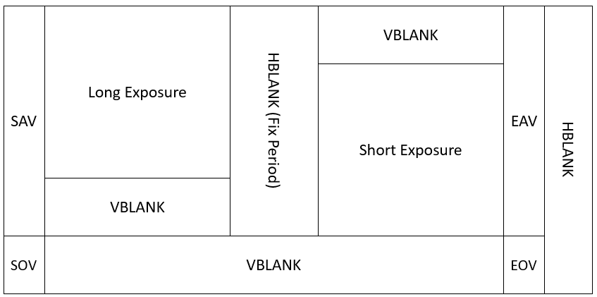
LVDS_VSYNC_HCONNECT |
long and short exposuresframea total ofshareoneforSAV-EAVidentifier, long and short exposuresframebetweenisfixedperiodblanking. |
Figure 1‑3 LVDS_VSYNC_NORMALsynchronization method.
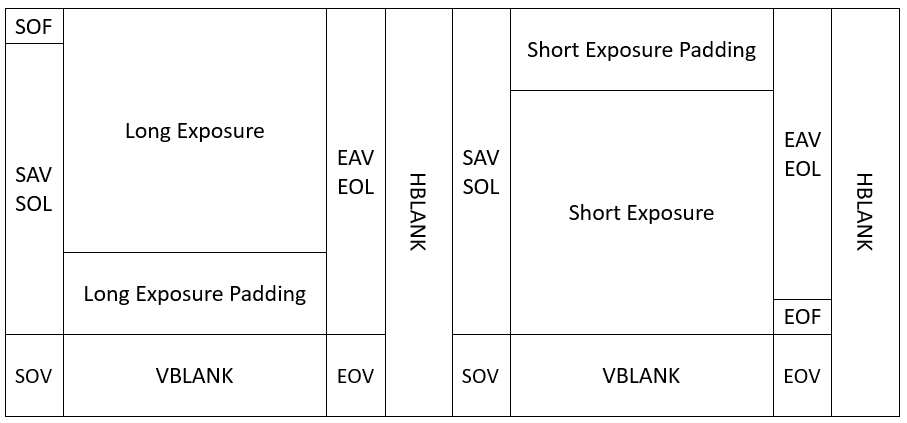
Figure 1‑4 LVDS_VSYNC_HCONNECTsynchronization method.
[Processor Differences]
None.
[Notes]
LVDS_VSYNC_NORMALsuitableused to SONY sub-LVDS DOL-2 pattern 1withHiSPi Packtized-SP WDRmode.
LVDS_VSYNC_SHAREsuitableused to HiSPi Streaming-SP WDRmode.
LVDS_VSYNC_HCONNECTsuitableused to SONY sub-LVDS DOL-2 pattern 2.
[Related data types and interfaces]
None
2.5.18. lvds_fid_type_e
[Description]
LVDS frame identification IDtype.
[Definition]
enum lvds_fid_type_e {
      LVDS_FID_NONE = 0,
      LVDS_FID_IN_SAV,
      LVDS_FID_BUTT,
};
[Members]
member |
Description |
|---|---|
LVDS_FID_NONE |
notuseframe identification id. |
LVDS_FID_IN_SAV |
FIDinsertinSAVNo. 4itemfieldin. |
[Processor Differences]
None.
[Notes]
None
[Related data types and interfaces]
None
2.5.19. lvds_fid_type_s
[Description]
LVDS frame identification IDtype.
[Definition]
struct lvds_fid_type_s {
        enum lvds_fid_type_e            fid;
};
[Members]
member |
Description |
|---|---|
fid |
LVDS DOLmodeunderframe identificationtype |
[Processor Differences]
None.
[Notes]
None
[Related data types and interfaces]
None
2.5.20. lvds_vsync_type_s
[Description]
LVDS WDRsynchronizationparameter.
[Definition]
struct lvds_vsync_type_s {
        enum lvds_vsync_type_e  sync_type;
        unsigned short                  hblank1;
        unsigned short                  hblank2;
};
[Processor Differences]
None.
[Notes]
When sync_typeisLVDS_VSYNC_HCONNECTwhen, need toconfigurehblank1andhblank2, meanslongshort exposurebetweenblankingarealength.
[Related data types and interfaces]
None
2.5.21. lvds_dev_attr_s
[Description]
LVDS/SubLVDS/HiSPideviceattribute.
[Definition]
struct lvds_dev_attr_s {
        enum wdr_mode_e                 wdr_mode;
        enum lvds_sync_mode_e           sync_mode;
        enum raw_data_type_e            raw_data_type;
        enum lvds_bit_endian            data_endian;
        enum lvds_bit_endian            sync_code_endian;
        short                           lane_id[MIPI_LANE_NUM+1];
        short   sync_code[MIPI_LANE_NUM][WDR_VC_NUM+1][SYNC_CODE_NUM];
        struct lvds_vsync_type_s        vsync_type;
        struct lvds_fid_type_s          fid_type;
        char                            pn_swap[MIPI_LANE_NUM+1];
};
[Members]
member |
Description |
|---|---|
wdr_mode |
WDRmode |
sync_mode |
LVDSsynchronizationmode |
raw_data_type |
transferData Types |
data_endian |
datasizesidemode |
sync_code_endian |
Synchronization Codesizesidemode |
lane_id |
sendside(sensor)andconnectreceiveside(MIPI Rx) lanecorrespondence |
sync_code |
eachVirtual Channelhas4itemSynchronization Code, according tosynchronizationmodenotsame, respectivelymeansSOF/EOF/ SOL/EOLSynchronization Codeororinvalid SAV/invalid EAV/ valid SAV/valid EAVSynchronization Code. |
vsync_type |
vsynctype, When wdr_modisDOLmodeandsync_modeisLVDS_SYNC_MODE_SAVwhen, need toconfigurevsynctype. |
fid_type |
frame identificationtype |
pn_swap |
Positive/negative line iswhether to swap |
[Processor Differences]
None.
[Notes]
None
[Related data types and interfaces]
None
2.5.22. dphy_s
[Description]
MIPI RX DPHY attribute.
[Definition]
struct mipi_dev_attr_s {
        unsigned char           enable;
        unsigned char           hs_settle;
};
[Members]
member |
Description |
|---|---|
enable |
Enable MIPI RX DPHYattributeset |
hs_settle |
hs settle time |
[Processor Differences]
None.
[Notes]
None
[Related data types and interfaces]
None
2.5.23. mipi_demux_info_s
[Description]
MIPI CSIuseVirtual Channel demultiplexingattributeset.
[Definition]
struct mipi_demux_info_s {
      unsigned int                    demux_en;
      unsigned char                   vc_mapping[MIPI_DEMUX_NUM];
};
[Members]
member |
Description |
|---|---|
demux_en |
Enable mipi virtual channel demultiplexing |
vc_mapping |
setISP channel withmipi virtual channelcorrespondence. for examplevc_mapping = {0, 2, 3, 1}, ISP ch0representvc=0; ch1representvc=2; ch2representvc=3; ch3representvc=1. |
[Processor Differences]
None.
[Notes]
None
[Related data types and interfaces]
None
2.5.24. mipi_dev_attr_s
[Description]
MIPI-CSIdeviceattribute.
[Definition]
struct mipi_dev_attr_s {
        enum raw_data_type_e            raw_data_type;
        short                           lane_id[MIPI_LANE_NUM+1];
        enum mipi_wdr_mode_e           wdr_mode;
        short                           data_type[WDR_VC_NUM];
        char                            pn_swap[MIPI_LANE_NUM+1];
};
[Members]
member |
Description |
|---|---|
wdr_mode |
WDRmode |
raw_data_type |
transferData Types |
lane_id |
sendside(sensor)andconnectreceiveside(MIPI Rx) lanecorrespondence |
data_type |
When WDRmodeisCVI_MIPI_WDR_MODE_DTwhen, eachWDR framescorrespondingdata type. |
pn_swap |
Positive/negative line iswhether to swap. |
[Processor Differences]
None.
[Notes]
None
[Related data types and interfaces]
None
2.5.25. manaul_wdr_attr_s
[Description]
manualWDRmodeparameter.
[Definition]
struct manaul_wdr_attr_s {
        unsigned int                    manual_en;
        unsigned short                  l2s_distance;
        unsigned short                  lsef_length;
        unsigned int                    discard_padding_lines;
        unsigned int                    update;
};
[Members]
member |
Description |
|---|---|
manual_en |
manualWDRswitch |
l2s_distance |
oneframeinfirstitemlong exposuretofirstcolumnshort exposuredistance, unitisnumber of lines. |
lsef_length |
long exposure/short exposurenumber of lines. |
discard_padding_lines |
SensoriswhetherhasthepaddinglineWhen validlineoutput. |
update |
iswhetherforcemorenewset. If whether, setwilletc.underonesynchronizationsignalonly whenmorenew. |
[Processor Differences]
None.
[Notes]
HiSPiinputandsync_typeisLVDS_VSYNC_SHAREwhen, need toenablemanualWDRmodeandsetparameter.
MIPI-CSIinputandwdr modeisCVI_MIPI_WDR_MODE_MANUALwhen, need toenablemanualWDRmodeandsetparameter.
[Related data types and interfaces]
None
2.5.26. ttl_pin_func_e
[Description]
TTL/BTconnectportconfigurefunction.
[Definition]
enum ttl_pin_func_e {
      TTL_PIN_FUNC_VS,
      TTL_PIN_FUNC_HS,
      TTL_PIN_FUNC_VDE,
      TTL_PIN_FUNC_HDE,
      TTL_PIN_FUNC_D0,
      TTL_PIN_FUNC_D1,
      TTL_PIN_FUNC_D2,
      TTL_PIN_FUNC_D3,
      TTL_PIN_FUNC_D4,
      TTL_PIN_FUNC_D5,
      TTL_PIN_FUNC_D6,
      TTL_PIN_FUNC_D7,
      TTL_PIN_FUNC_D8,
      TTL_PIN_FUNC_D9,
      TTL_PIN_FUNC_D10,
      TTL_PIN_FUNC_D11,
      TTL_PIN_FUNC_D12,
      TTL_PIN_FUNC_D13,
      TTL_PIN_FUNC_D14,
      TTL_PIN_FUNC_D15,
      TTL_PIN_FUNC_NUM,
};
[Processor Differences]
None.
[Notes]
None
[Related data types and interfaces]
None
2.5.27. ttl_src_e
[Description]
TTL/BTconnectportinputtosource.
[Definition]
enum ttl_src_e {
      TTL_VI_SRC_VI0 = 0,
      TTL_VI_SRC_VI1,
      TTL_VI_SRC_VI2,         /* BT demux */
      TTL_VI_SRC_NUM
};
[Processor Differences]
None.
[Notes]
None
[Related data types and interfaces]
referenceTable 1-1.
2.5.28. bt_demux_mode_e
[Description]
BTdemultiplexingmodechannelnumber.
[Definition]
enum bt_demux_mode_e {
      BT_DEMUX_DISABLE = 0,
      BT_DEMUX_2,
      BT_DEMUX_3,
      BT_DEMUX_4,
};
[Processor Differences]
None.
[Notes]
None
[Related data types and interfaces]
None
2.5.29. bt_demux_sync_s
[Description]
BTdemultiplexingmodeSynchronization Codeset.
[Definition]
struct bt_demux_sync_s {
      unsigned char           sav_vld;
      unsigned char           sav_blk;
      unsigned char           eav_vld;
      unsigned char           eav_blk;
};
[Members]
member |
Description |
|---|---|
sav_vld |
validdatarangeSAV |
sav_blk |
blankrangeSAV |
eav_vld |
validdatarangeEAV |
eav_blk |
blankrangeEAV |
[Processor Differences]
None.
[Notes]
None
[Related data types and interfaces]
None
2.5.30. bt_demux_attr_s
[Description]
BTdemultiplexingmodeattributeset.
[Definition]
struct bt_demux_attr_s {
      signed char                     func[TTL_PIN_FUNC_NUM];
      unsigned short                  v_fp;
      unsigned short                  h_fp;
      unsigned short                  v_bp;
      unsigned short                  h_bp;
      enum bt_demux_mode_e            mode;
      unsigned char                   sync_code_part_A[3];    /* sync code 0~2 */
      struct bt_demux_sync_s          sync_code_part_B[BT_DEMUX_NUM]; /* sync code 3 */
      char                            yc_exchg;
};
[Members]
member |
Description |
|---|---|
func |
BTconnectportcorrespondinginputsourceTTL_VI_SRC_VI2lane number. IndexisBTlogicfunction, valuepleasereferenceTable 1-1. for example, func[TTL_PIN_FUNC_D0] = 5, representBTsignalD0connecttoVI2_D[5], that is, pad name VIVO_D5. |
v_fp |
verticaldirectionfront porch |
h_fp |
horizontaldirectionfront porch |
v_bp |
verticaldirectionback porch |
h_bp |
horizontaldirectionback porch |
mode |
BTdemultiplexingmodechannelnumber |
sync_code_part_A |
BTdemultiplexingmode0~2Synchronization Code |
sync_code_part_B |
BTdemultiplexingmodeSynchronization Code3 |
yc_exchg |
BIT0~BIT3respectivelyrepresentCH0~CH3Y Cb/Cr bytesorderswap. 1 isswap, 0 isnotswap. |
[Processor Differences]
None.
[Notes]
None
[Related data types and interfaces]
None
2.5.31. ttl_dev_attr_s
[Description]
TTL/BTconnectportattributeset.
[Definition]
struct ttl_dev_attr_s {
      enum ttl_src_e                  vi;
      signed char                     func[TTL_PIN_FUNC_NUM];
      unsigned short                  v_bp;
      unsigned short                  h_bp;
};
[Members]
member |
Description |
|---|---|
vi |
TTL/BTconnectportinputtosource, allowvalueisTTL_VI_SRC_VI0orTTL_VI_SRC_VI1 |
func |
BTconnectportcorrespondinginputsourcelane number. IndexisBTlogicfunction, valuepleasereferenceTable 1-1. for example, vi = TTL_VI_SRC_VI1when, func[TTL_PIN_FUNC_D0] = 5, representBTsignalD0connecttoVI1_D[5], that is, pad name VIVO_D5. |
v_bp |
verticaldirectionback porch |
h_bp |
horizontaldirectionback porch |
[Processor Differences]
None.
[Notes]
None
[Related data types and interfaces]
None
2.5.32. combo_dev_attr_s
[Description]
combo deviceattribute, byinMIPI Rxcansufficient forconnectCSI-2, sub-LVDS, HiSPietc.timing, thereforewillMIPI Rxcalliscombodevice.
[Definition]
struct combo_dev_attr_s {
       enum input_mode_e            input_mode;
       enum rx_mac_clk_e             mac_clk;
       struct mclk_pll_s                mclk;
       union {
               struct mipi_dev_attr_s  mipi_attr;
               struct lvds_dev_attr_s  lvds_attr;
               struct ttl_dev_attr_s   ttl_attr;
               struct bt_demux_attr_s  bt_demux_attr;
       };
       unsigned int                  devno;
       struct img_size_s              img_size;
       struct manaul_wdr_attr_s        wdr_manu;
};
[Members]
member |
Description |
|---|---|
input_mode |
inputconnectporttype |
mac_clk |
MIPI RX MACclockset |
mclk |
MIPI RXoutputSensorreferenceclockset |
mipi_attr |
If input_modeconfigureisINPUT_MODE_MIPI, thenmustconfiguremipi_attr |
lvds_attr |
If input_modeconfigureisINPUT_MODE_SUBLVDS/INPUT_MODE_HISPI, thenmustconfigurelvds_attr |
devno |
MIPI-Rxdevicenumber |
img_size |
inputframesize |
wdr_manu |
manualWDRattribute |
[Processor Differences]
None.
[Notes]
None
[Related data types and interfaces]
None
2.5.33. crop_top_s
[Description]
discard leadinglinedata.
[Definition]
struct crop_top_s {
        unsigned int                    devno;
        unsigned int                    crop_top;
        unsigned int                    update;
};
[Members]
member |
Description |
|---|---|
devno |
MIPI-Rxdevicenumber |
crop_top |
openheaderneed todiscardnumber of lines |
update |
iswhetherforcemorenewset. If whether, setwilletc.underonesynchronizationsignalonly whenmorenew. |
[Processor Differences]
None.
[Notes]
None
[Related data types and interfaces]
None
2.5.34. manual_wdr_s
[Description]
manualWDRmodeset.
[Definition]
struct manual_wdr_s {
        unsigned int                  devno;
        struct manaul_wdr_attr_s        attr;
};
[Members]
member |
Description |
|---|---|
devno |
MIPI-Rxdevicenumber |
attr |
manualWDRattribute |
[Processor Differences]
None.
[Notes]
None
[Related data types and interfaces]
None
2.5.35. vsync_gen_s
[Description]
manualWDRmodeset.
[Definition]
struct vsync_gen_s {
        unsigned int                    devno;
        unsigned int                    distance_fp;
};
[Members]
member |
Description |
|---|---|
devno |
MIPI-Rxdevicenumber |
distance_fp |
When input_modeisINPUT_MODE_SUBLVDSwhen, generateverticalsynchronizationsignaltimepoint. |
[Processor Differences]
None.
[Notes]
Sub-LVDSnotbuilt-inverticalsynchronizationsignal, thereforeMIPI-RxmustmanuallygeneratesendgiveISP. distance_fp adjustableentireverticalsynchronizationtimepointwithreachaddlargefront porchoperationuse.
[Related data types and interfaces]
None
2.5.36. LANE_MAX_NUM
[Description]
oneMIPI TxdevicesupportsmaximumLanenumber.
[Definition]
#define MIPI_LANE_NUM 4
[Processor Differences]
None.
[Notes]
None
[Related data types and interfaces]
None
2.5.37. output_mode_e
[Description]
MIPI Txoutputmode.
[Definition]
enum output_mode_e
{
  OUTPUT_MODE_CSI             = 0x0,      /* csi mode */ OUTPUT_MODE_DSI_VIDEO      = 0x1,      /* dsi video mode */
  OUTPUT_MODE_DSI_CMD       = 0x2,      /* dsi command mode */
  OUTPUT_MODE_BUTT
} output_mode_t;
[Processor Differences]
None
[Notes]
None
[Related data types and interfaces]
None
2.5.38. video_mode_e
[Description]
MIPI Txvideomode.
[Definition]
enum video_mode_e {
   BURST_MODE                      = 0x0,
   NON_BURST_MODE_SYNC_PULSES      = 0x1,
   NON_BURST_MODE_SYNC_EVENTS      = 0x2,
};
[Processor Differences]
None
[Notes]
None
[Related data types and interfaces]
None
2.5.39. output_format_e
[Description]
LVDS inWDRmodesynchronization method.
[Definition]
enum output_format_e {
   OUT_FORMAT_RGB_16_BIT          = 0x0,
   OUT_FORMAT_RGB_18_BIT          = 0x1,
   OUT_FORMAT_RGB_24_BIT          = 0x2,
   OUT_FORMAT_RGB_30_BIT          = 0x3,
   OUT_FORMAT_YUV420_8_BIT_NORMAL = 0x4,
   OUT_FORMAT_YUV420_8_BIT_LEGACY = 0x5,
   OUT_FORMAT_YUV422_8_BIT        = 0x6,

   OUT_FORMAT_BUTT
};
[Processor Differences]
Processor Differences |
iswhethersupport |
|---|---|
CV181x |
Not supportedYUV420 |
CV180x |
Not supportedYUV420 |
[Notes]
None
[Related data types and interfaces]
None
2.5.40. sync_info_s
[Description]
MIPI Txdevicesynchronizationinformation.
[Definition]
struct sync_info_s {
   unsigned short  vid_hsa_pixels;
   unsigned short  vid_hbp_pixels;
   unsigned short  vid_hfp_pixels;
   unsigned short  vid_hline_pixels;
   unsigned short  vid_vsa_lines;
   unsigned short  vid_vbp_lines;
   unsigned short  vid_vfp_lines;
   unsigned short  vid_active_lines;
   unsigned short  edpi_cmd_size;
   bool            vid_vsa_pos_polarity;
   bool            vid_hsa_pos_polarity;
};
[Members]
member |
Description |
|---|---|
vid_hsa_pixels |
Horizontal sync-plusepixelcount |
vid_hbp_pixels |
Horizontal back-porchpixelcount |
vid_hfp_pixels |
Horizontal front-porchpixelcount |
vid_hline_pixels |
Horizontal image activepixelcount |
vid_vsa_lines |
Vertical sync-plusenumber of lines |
vid_hbp_pixels |
Vertical back-porchnumber of lines |
vid_hbp_pixels |
Vertical front-porchnumber of lines |
vid_active_pixels |
Vertical image activenumber of lines |
edpi_cmd_size |
writememorycommandbytesnumber. video modewhenthevalueinvalid, command modewhenthevaluesetishact. |
vid_vsa_pos_polarity; |
Horizontal sync-pluse polarity |
vid_hsa_pos_polarity; |
Vertical sync-pluse polarity |
[Processor Differences]
None.
[Notes]
None
[Related data types and interfaces]
None
2.5.41. combo_dev_cfg_s
[Description]
MIPI Txdeviceattribute.
[Definition]
struct combo_dev_cfg_s {
    unsigned int            devno;
    enum mipi_tx_lane_id    lane_id[LANE_MAX_NUM];
    enum output_mode_e      output_mode;
    enum video_mode_e       video_mode;
    enum output_format_e    output_format;
    struct sync_info_s      sync_info;
    unsigned int            phy_data_rate;
    unsigned int            pixel_clk;
    bool                    lane_pn_swap[LANE_MAX_NUM];
};
[Members]
member |
Description |
|---|---|
devno |
devno |
lane_id |
sendside(vo)andconnectreceiveside(MIPI Tx) Lanecorrespondence;unuseduseLanesetis-1. |
output_mode |
MIPI Txoutputmode. |
video_mode |
MIPI Txvideomode. |
output_format |
MIPI Txoutputformat. |
sync_info |
MIPI Tx device synchronization information. |
phy_data_rate |
MIPI Txoutputrate, MIPI Txhighspeedmodeeachchannel (lane) raterangeDescription. |
pixel_clk |
pixelclock. unitisKHz |
lane_pn_swap |
LanesetoniswhetherP/Nneed toswap |
[Processor Differences]
None.
[Notes]
None
[Related data types and interfaces]
2.5.42. cmd_info_s
[Description]
giveMIPI Txdeviceinitializationinformation.
[Definition]
struct cmd_info_s {
    unsigned int        devno;
    unsigned short      data_type;
    unsigned short      cmd_size;
#ifdef __arm__
    unsigned char       *cmd;
    unsigned int       padding;
#else
    unsigned char       *cmd;
#endif
};
[Members]
member |
Description |
|---|---|
devno |
MIPI Txdevicenumber |
data_type |
commandData Types |
cmd_size |
commanddatabytesnumber, range: (0,128). |
cmd_data |
commanddataaddresspointer, need touserallocate. |
[Processor Differences]
None.
[Notes]
None
[Related data types and interfaces]
2.5.43. get_cmd_info_s
[Description]
fromMIPI Txdeviceretrieveinformation.
[Definition]
struct get_cmd_info_s {
    unsigned int        devno;
    unsigned short      data_type;
    unsigned short      data_param;
    unsigned short      get_data_size;
#ifdef __arm__
    unsigned int        padding1;
    unsigned char       *get_data;
    unsigned int        padding2;
#else
    unsigned int        padding1;
    unsigned char       *get_data;
#endif
};
[Members]
member |
Description |
|---|---|
devno |
MIPI Txdevicenumber |
data_type |
commandData Types |
data_param |
dataparameter, loweightbitisfirstitemparameter, higheightbitisseconditemparameter, notusewhenfill0 |
get_data_size |
expectedgetdatabytesnumber, range: (0,4). |
get_data |
gettodatastoreaddresspointer, need touserallocate. |
[Processor Differences]
None.
[Notes]
None
[Related data types and interfaces]
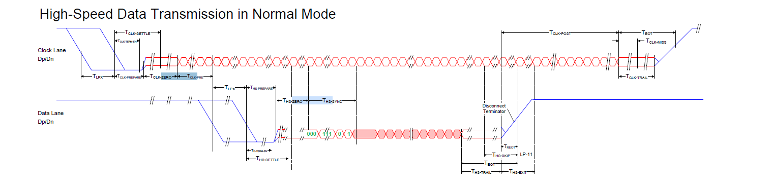
2.5.44. hs_settle_s
[Description]
MIPI TxdeviceHS modeundersettleinformation.
[Definition]
struct hs_settle_s {
    unsigned char       prepare;
    unsigned char       zero;
    unsigned char       trail;
};
[Members]
member |
Description |
|---|---|
prepare |
isLP->HSafterbeforesetpreparationTnumber |
zero |
inenterHSafter, inoutputdatabeforeis0Tnumber |
trail |
inHS->LPwhen, need toendHSbefore, dataendafteradditionaloutsideTnumber |
[Processor Differences]
None.
[Notes]
[Related data types and interfaces]
None
2.6. Procinformation
2.6.1. MIPI_RX Procinformation
MIPI_Rxinnormalworkingunderprocinformationineachtypeerrorinterruptcountshouldis0. If whether, pleasecheckMIPI_Rxrelatedattributeiswhetherconfigurecorrect.
[Debug Information]
Module: [MIPI_RX], Build Time[#1 SMP PREEMPT Thu Apr 29 11:18:57 CST 2021]

------------Combo DEV ATTR--------------
 Devno  WorkMode  DataType   WDRMode         LinkId        PN Swap  SyncMode  DataEndian  SyncCodeEndian
     0      MIPI     RAW12      NONE  2, 3, 1, 4, 0  1, 1, 1, 1, 1       N/A         N/A             N/A

------------MIPI info-------------------
Devno EccErr CrcErr HdrErr WcErr fifofull   decode
   0      0      0      0     2        0    raw12
Physical:       D0       D1       D2       D3       D4       D5
                 0        0        0        0        0        0
 Digital:       D0       D1       D2       D3    CK_HS  CK_ULPS  CK_STOP   CK_ERR   Deskew
           hs_idle  hs_idle  hs_idle  hs_idle        1        0        0        0     idle
[debuginformationanalysis]
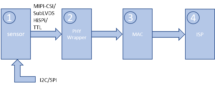
MIPI RxthroughPHY WrapperconnectreceiveSensorMIPI-CSI/SubLVDS/HiSPi/TTLsignal, byMACincorrespondingconnectportperform synchronizationheader detectionwithalignment.
MACwilleachLanedatacombinedandbecomePixeldata, andwilldatasendgiveafterlevelISP.
PHY Wrapperbysensorpixel clockprovideclock. MACinclockwithafterlevelISPsame.
If need tooperationdataCrop, can byafterlevelISPtodebug.
Figure 1‑5datashowexampleFigure
[Parameter Description]
Parameters |
Description |
|
|---|---|---|
MIPI DEV ATTR |
Devno |
MIPIdevicenumber |
WorkMode |
MIPIdeviceoperating mode: MIPI/ SUBLVDS/HISPI/CMOSetc.mode |
|
DataType |
RAW8/RAW10/RAW12etc.type |
|
WDRMode |
|
|
LaneId |
Lane id |
|
PN Swap |
PN signalswap |
|
LVDS DEV ATTR |
Devno |
MIPIdevicenumber |
WorkMode |
MIPIdeviceoperating mode: MIPI/ SUBLVDS/HISPI/CMOSetc.mode |
|
DataType |
RAW8/RAW10/RAW12etc.type |
|
WDRMode |
|
|
LaneId |
Lane id |
|
PN Swap |
PN signalswap |
|
SyncMode |
|
|
DataEndian |
Databitbitssizesidemode |
|
SyncCodeEndian |
Synchronization Codebitbitssizesidemode |
|
MIPI Info (onlyMIPImodecan see) |
Devno |
MIPIdevicenumber |
EccErr |
ECCerrorinterruptcount |
|
CrcErr |
CRCerrorinterruptcount |
|
HdrErr |
HDR Flagerrorinterruptcount |
|
WcErr |
Word Counterrorinterruptcount |
|
fifofull |
Fifofull interruptcount |
|
Physical: D0 |
MIPIRX_PAD0 receivetodata |
|
Physical: D1 |
MIPIRX_PAD1 receivetodata |
|
Physical: D2 |
MIPIRX_PAD2 receivetodata |
|
Physical: D3 |
MIPIRX_PAD3 receivetodata |
|
Physical: D4 |
MIPIRX_PAD4 receivetodata |
|
Physical: D5 |
MIPIRX_PAD5 receivetodata |
|
Digital: D0 |
Sensor data lane 0 state |
|
Digital: D1 |
Sensor data lane 1 state |
|
Digital: D2 |
Sensor data lane 2 state |
|
Digital: D3 |
Sensor data lane 3 state |
|
CK_HS/CK_ULPS/CK_STOP/CK_ERR |
Sensor clock lane state |
|
Deskew |
Deskew result |
|
2.7. FAQ
2.7.1. 1.6.1. Land idhow to configure
Land idconfigurecorrespondingmipi_dev_attr_sinshort lane_id[MIPI_LANE_NUM+1]ororlvds_dev_attr_sMedium short lane_id[MIPI_LANE_NUM+1], wherelane_idarrayindexnumbermeansisSensorLane ID, indexnumber 0meanssensor clock, indexnumber1meanssensor lane 0. land_idarrayvaluemeansisMIPI-RxLane ID, 0meansMIPIRX1_PAD0, 1meansMIPIRX1_PAD1. unuseduselanewillitscorrespondinglane_idconfigureis-1.
belowExampledescription, for exampleMIPIwithSENSORpinhardwareconnectconnectas followsTable shown.
SENSORpin |
MIPI Lanepin |
|---|---|
Clock Lane (index = 0) |
MIPIRX1_PAD0 (value = 0) |
Lane 0 (index = 1) |
MIPIRX1_PAD1 (value = 1) |
Lane 1 (index = 2) |
MIPIRX1_PAD2 (value = 2) |
Lane 2 (index = 3) |
MIPIRX1_PAD3 (value = 3) |
Lane 3 (index = 4) |
MIPIRX1_PAD4 (value = 4) |
MIPImaximumLanenumberaddonClockis5, thereforelane_idconfigureas follows:
//索引sensor_clk,   sensor_lane0,  sensor_lane1,  sensor_lane2,    sensor_lane3
//          ↓               ↓            ↓            ↓               ↓
land_id={MIPIRX1_PAD0  MIPIRX1_PAD1  MIPIRX1_PAD2  MIPIRX1_PAD3 MIPIRX1_PAD4 }
2.7.2. MIPIfrequencydescription
usewithunderformulacalculateMIPIeachLanemosthighfrequencywithVI MACworkingfrequency:
MAC_Freq * pixel_width = lane_num * MIPI_Freq * 2. whereMAC_FreqisVI MACworkingfrequency, pixel_widthispixelbit width, lane_numisMIPI lanecount, MIPI_Freqiseachitemlaneworkingfrequency. If MAC clockis400M, pixel_width = 12, lane_num = 4, can supportmostfastMIPI_Freq = 400 * 12 / ( 4 * 2) = 600MHz.
2.7.3. Manual WDRmodeusedescription
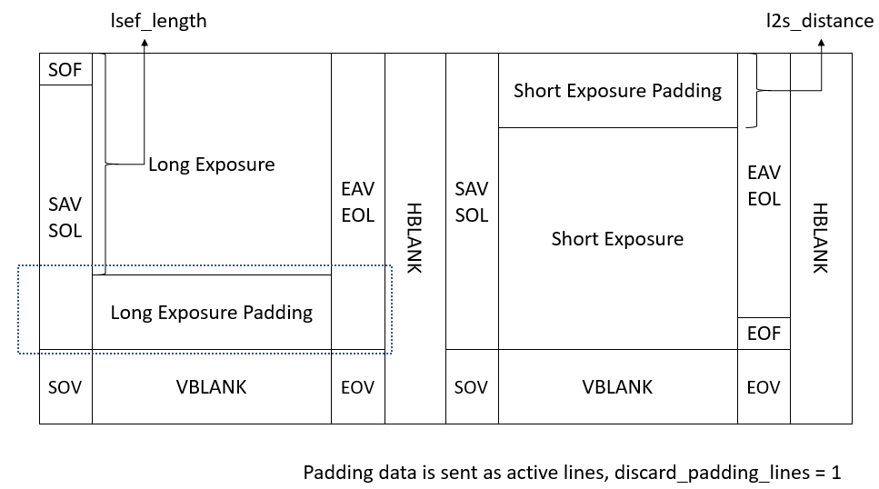
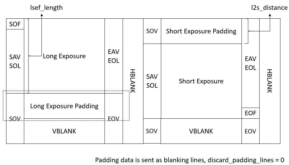
When manualWDRmodeenableafter, MIPI-Rxwillthereceiveundertodatawithlineisunit, followwithunderrulethenallocategivelong exposureframewithshort exposureframe.
l2s_distance: fromfirstlinetoNo. l2s_distancelineallislong exposuredata, No. l2s_distance+1linestartlong exposurewithshort exposureinterleavedallocate.
lsef_length: No. lsef_length+1linestartallisshort exposureframedata. directlytounderitemverticalsynchronizationsignalisstop.
When discard_padding_lines=1when, 1tol2s_distancelineallocatemethodis{long-ignore-long-ignore ...}, No. l2s_distance+1tolsef_lengthlineallocatemethodis{long-short-long-short ...}. No. lsef_length+1linetounderitemverticalsynchronizationsignalallocatemethodis{short-ignore-short-ignore ...}.
When discard_padding_lines=0when, 1tol2s_distancelineallocatemethodis{long-long-long ...}, No. l2s_distance+1tolsef_lengthlineallocatemethodis{long-short-long-short ...}. No. lsef_length+1linetounderitemverticalsynchronizationsignalallocatemethodis{short-short-short ...}.
MIPI-RxmustensuresendgiveISPlong exposureframewithshort exposureframenumber of linesisonecause.
adjustsensorshort exposurelength, hasmayl2s_distanceneed toonestartadjust.
hassomesensormaywillinsendcompleteshort exposurevaliddataafterwithdummyline. thiswillcauselong exposurewithshort exposurenumber of linesnotonecause. can willl2s_distanceset to0, lsef_lengthset tomaximumvalue0x1FFF, discard_padding_linesis1that is, receiveundertwo withvalidwithdummydatalongshort exposure, thenuseISP cropvalidpositionthat is, can .
