4.2. Design Overview
4.2.1. System Architecture
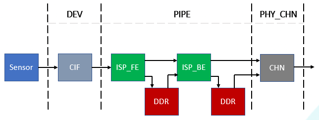
VI fromsoftwareonInputDevice (DEV), imagecapture (ISP_FE), Imageprocessing (ISP_BE) andimagecorrection (CHN) fouritemlayerlevel.
SensortransmitimagethroughCIFforconnect, willimagegiveISP_FE, ISP_FEwillcaptureAE, AWB, AFetc.statisticsvaluedata, andwillRAWFilestoragetoDDRon, thenthroughISP_BEUseOnlineorMode, willRAWFileperform color gamutConversionandImagequalityadjust, connectwithwillYUVstorageinDDR, andprovideafterendCHNperform Crop, Rotationetc.processing.
beforeProcessorDeviceParameterConfigurationas shown in the following table.
Processor | DEV | PHY_PIPE | PHY_CHN | VIR_CHN | MAX resolution | FPS |
|---|---|---|---|---|---|---|
CV184x | 3 | 3 | 3 | 0 | 8M(3840x2160) | 30 |
Note
None.
4.2.2. Video Input PIPE
VI PIPE including ISP RelatedprocessingFunction, mainisforImageDataperform streamprocessing, Output YUV ImageFormatgiveChannel. PIPE Operating modePlease refer to“System Control”section“VI and VPSS” Operating modeDescription.
4.2.3. Video Physical Channel
eachPhysicalChannelhasCropFunction, Supportresolutionif 3840x2160@30fps, 2880x2160@30fps, 2688x1520@30fps, 1080p@30fps etc..
4.2.4. Binding Relationships
DevandCIFBinding Relationshipsisfixed, notcandynamicmodifyBinding Relationships.
DevandtimingInputInterfacerelationshipas shown in the following table.
VI DEV | MIPI | SLVS | BT.1120/BT.656/BT.601 | DC | TTL |
|---|---|---|---|---|---|
0 | 0 | 0 | 0 | X | X |
1 | 1 | 1 | 1 | X | X |
2 | X | X | X | X | 2 |